Figure 2 Isokinetic probe function
1 No probe in non-laminar air flow 3 No probe in laminar air flow—
particles are missed
2 To particle counter 4 Isokinetic probe in laminar air flow
—most accurate
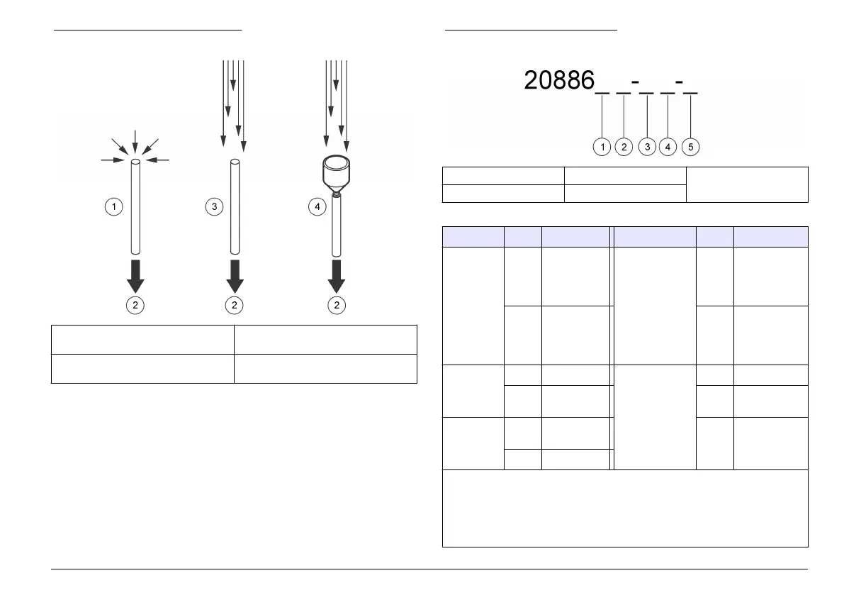
Instrument configurations
This instrument is available in many configurations. Each configuration
has a different part number. Figure 3 shows the part number structure.
Table 3 gives descriptions of the part number codes.
Figure 3 Part number structure
1 Flow rate 3 Exhaust location 5 Communication
2 Sensitivity (minimum) 4 Flow measurement
Table 3 Parameter codes
Parameter Code Description Parameter Code Description
Flow rate 0 0.1 cfm
(for 0.3 µm
and 0.5 µm
sensitivity)
Flow
measurement
F With flow
measurement
1 1.0 cfm
(for 0.5 µm
sensitivity
only)
N Without flow
measurement
Sensitivity
(minimum)
3 0.3 µm Communication E Ethernet
5 0.5 µm S Serial I/O
options
Exhaust
location
D Down
(bottom)
A Analog
S Side
Example: An instrument with a 0.1 cfm flow rate, 0.5 μm sensitivity, bottom
exhaust port, flow measurement and RS485 communication will have the part
numbers 2088605-DF-S and 20888600-485. The second part number is
necessary to identify the type of serial communication (RS232 = 20888600-232,
RS485 = 20888600-485 or Pulse = 20888600-PLS). The second part number is
not necessary for any other communication type.
English 7
 Loading...