10
ボタンを一度押す
ボタンを一度押す
またはボタンを押す
温度設定モード
またはボタンを押す
ボタンを一度押す
ボタンを一度押す
●こて先温度のオフセット
例:D チャンネルの設定温度が 400℃で、実
際のこて先温度が 410℃の場合
設定温度との差は 10℃であるため現在の
オフセット値として -10 を入力します。
1.
表示が D チャンネルであることを確認します。
●S チャンネルを表示している場合は ボタ
ンを押して切り替えます。
2.カードをステーションに差し込む
●温度設定モードに入ります。
3. ボタンを押す
●オフセットモードに入ります。
または ボタンを用い、3 桁目の数値を
決定します。
入力可能な数値は 0(プラスの場合)と−(マ
イナスの場合)です(℉モードも同じです)。
4.
または を選択し ボタンを押す
点滅が 2 桁目に移ります。オフセット値を
入力します。
入力可能な数値は 0 〜 5 です ( ℉モード時
は0〜9です)。
2 桁目以降はオフセット値入力範囲で設定し
ます。
オフセット値入力可能範囲
℃
・・・・・・・-
50 〜+ 50℃
℉
・・・・・・・-
90 〜+ 90 ℉
オフセット値入力可能範囲を超える数値を
入力すると再度 3 桁目に戻りますので、正
しい数値を入れ直してください。
注意
オフセット入力モード時(点滅している時)は、現
在のオフセット値で制御されます。
5.こて先温度を確認します。
注記:
・
オフセット値はこて部の種類毎に値を保存しています。
ハッコー FM-2027 を接続してオフセット値(例え
ば
-
10℃)を入力し次にモデル FM-2023 に差し替
えてオフセット値(例えば
-
20℃)を入力します。
その後、再度ハッコー FM-2027 を差し替えた場合、
オフセット値は自動的に
-
10℃となります。
・
オフセットはチャンネル毎に値を保存していきます。
D チャンネルと S チャンネルにハッコー FM-2027
を接続してオフセット値を入力した場合、それぞれ
のハッコー FM-2027 は個別のオフセット値で制御
されます。ただし、D チャンネルでオフセット値を
設定したハッコー FM-2027 を S チャンネルに接続
しても、D チャンネルのオフセット値は S チャンネ
ルには反映されません。
73
●
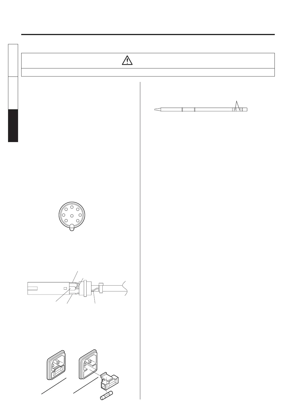
Checking Procedure
■
Check for a broken heater or
sensor
1. Check for a broken heater or sensor
across this position.
Verify the electrical integrity of the heater and
sensor.
Measure the resistance of the heater and sensor
while at room temperature (15 to 25°C; 59 to
77°F). It should be 8
Ω
±10%. If the resistance
exceeds these limits, replace the tip.
■
Check the grounding line
1. Unplug the connection cord from the station.
2. Measure the resistance value between Pin 2 and
the tip.
3. If the value exceeds 2
Ω
(at room temperature),
perform the tip maintenance described on p.16.
If the value still does not decrease, check the
connection cord for breakage.
■
Checking the connection cord
for breakage
1. Remove the soldering tip and the sleeve
assembly.
2. Turn the front piece of the HAKKO FM-2027
clockwise and remove the cover.
3. Measure the resistance values between the
connector and the lead wires at the socket as
follows:
Pin 1 − Red Pin 2 − Green
Pin 3 − Black Pin 5 − White
If any value exceeds 0
Ω
or is
∞
, replace the
HAKKO FM-2027.
White
Green
Red
■
Replacing the fuse
1. Unplug the power cord from the power
receptacle.
2. Remove the fuse holder.
3. Replace the fuse.
4. Put the fuse holder back in place.
WARNING
Unless otherwise directed, carry out these procedures with the power switch OFF and the power UNPLUGGED.
English
中文 日本文
日本文 中文
English