23
12.こて先の種類
ø0.8
ø0.8
60°
12
30°
R0.2
3.5
12
30°
7.5
R0.2
9.3
45°
ø4.7
17
4.6
4.5
2.3
6.7
5.1
10.4
4.5
2.3
6.7
5.1
18.3
5.5
3.2
11.1
9.5
15.8
5.5
3.2
11.1
9.5
13.2
5.5
3.2
11.1
9.5
11.4
4.5
2.3
8.7
6.9
18.8
5.5
3.2
9.3
7.9
10.2
6
3
20.9
19.5
20.5
6
4.3
14.8
13.4
12
6
3
20.9
19.5
2
ø4.7
45°
15
ø4.7
1.5
45°
11
45°
ø4.7
1.5
11
45°
ø3
1.2
11
7.9
1.6
R0.2
30°
R0.2
12.7
9.5
R0.2
R0.15
13.5
1.2
ø5.2
9
16
0.5
ø3.2
7
10
ø1.2
0.6
3
13
ø0.8
0.6
3
13
ø5.2
1.2
7
8
0.5
ø0.8
3.2
9.5
0.5
ø1.2
3
10
ø1.6
0.5
3.5
10
0.5
ø2.4
4
10
0.5
ø4
4
8.5
1
ø1
60°
12
ø4
45º
11.5
ø2
2.1
45
°
11.5
ø1
1.1
11.5
45
°
3.3
ø3
10
45
°
5
R0.4
5
R0.7
R0.5
10
R0.2
7.5
R0.2
12
115
139
ø5.5
単位:mm
T12-BL BL型T12-B4 0.4B型T12-B3 0.7B型T12-B2 0.5B型T12-B B型
T12-BCF3 3BC
型 面のみ
T12-BC3 3BC
型
T12-BCF2 2BC
型 面のみ
T12-BC2 2BC
型
T12-BCF1 1BC
型 面のみ
T12-BC1 1BC
型
T12-CF4 4C
型 面のみ
T12-C4 4C型T12-C1 1C型T12-C08 0.8C型
T12-D12 1.2D
型
T12-D08 0.8D
型
T12-DL52 5.2DL
型
T12-DL32 3.2DL
型
T12-DL12 1.2DL
型
T12-DL08 0.8DL
型
T12-D52 5.2D
型
T12-D4 4D
型
T12-D24 2.4D
型
T12-D16 1.6D
型
T12-ILS ILS型
T12-KF KF型T12-K K型
T12-JS02 0.2JS型T12-JL02 0.2JL型T12-J02 0.2J型
T12-IL IL型T12-I I型
T12-1010 トンネル 19.5 × 12T12-1009 トンネル 13.4 × 20.5T12-1008 トンネル 19.5 × 10.2T12-1007 トンネル 7.9 × 18.8T12-1006 トンネル 6.9 × 11.4
T12-1005
トンネル 9.5 × 13.2T12-1004 トンネル 9.5 × 15.8T12-1003 トンネル 9.5 × 18.3T12-1002 トンネル 5.1 × 10.4T12-1001 トンネル 5.1 × 4.6
T12-KU KU
型T12-KR KR型T12-KL KL型
60
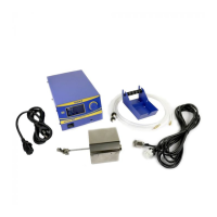
Connecting cable
Jack to Connecting cable
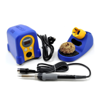
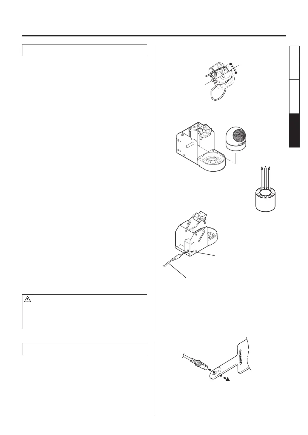
A. Iron holder
●
Loosen the adjusting screws to change the
angle of the iron receptacle as you like, then
tighten the screws.
1. Assemble as shown:
●
Insert the holder assembly securely into the
Iron holder base.
2. Operation:
First, remove any excess solder from the tip by
thrusting the tip into the cleaning wire.
(Do not wipe the tip against the wire. This may
cause molten solder to spatter.)
When the wire becomes dirty or loaded with
solder, turn the wire until a clean surface is
presented.
When changing the cleaning wire, lift the case
top vertically to prevent solder debris from
falling out.
3. Place the spare tips in the tip tray.
●
Use of the sleep function
When using the sleep function, insert one end
of the connecting cable into the jack at the
back of the iron holder and the other end into
the jack at the back of the soldering station to
connect them.
CAUTION
• Be sure to turn off the power before connecting or
disconnecting the connecting cable.
• Securely insert the connecting cable all the way in to the
jack.
B. Connector cord
●
Pass the connector cord through the hole in
the heat resistant pad.
4. INITIAL SETUP
English
中文 日本文
日本文 中文
English