33
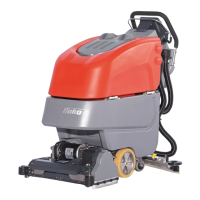
Operation
Solution tank filling neck(Fig. 11/ 1)
The solution tank is filled through a de-
tachable filling neck. The fill level can
be seen through the draining hose.
Squeegee lift hand lever (Fig. 11/2)
Use the hand lever to lower or lift the
sque
egee. On Scrubmaster B45 CL
machines, this also turns the suction
turbine on/off.
Solution filter (Fig. 11/3)
When the solution is fed from the solu-
tion
tank to the brush head, the solution
is cleaned by a filter insert.
Solution draining hose (Fig. 11/4)
The solution tank draining hose is used
to
drain the solution.
Power supply line (Fig. 11/5)
The power supply line feeds power to
th
e charger. Following completion of
the charging process, insert the ground-
ed plug firmly in the holder with the inte-
grated machine immobilizer.
Brush head lift foot pedal (Fig. 11/6)
This pedal raises and lowers the brush
hea
d.
Waste water draining hose (Fig. 11/
7)
Use this hose to drain any waste water
previously drawn up into the waste wa-
ter tank.
Solution hand valve (Fig. 11/8)
Scrubmaster B45 features a hand valve
fo
r adjusting the amount of water sup-
plied to the brush head. The solution
quantity can be regulated between 0 l/
min and 1.85 l/min.