49
Subject to change without notice
Structure and using of the me-
[OFFS] (Offset)
Offset: 1.00 V
- val + < cur >
The amplitude can be entered either as a peak-to-peak value in
V
pp
or as a rms value in V
rms
, selectable by the button pp/rms of
the keyboard. Please note that an indication of V
pp
or V
rms
will
not be valid for arbitrary functions, also, any offset superposed
will not be included.
If a 50 ohm load is connected the actual amplitude
will be half of the displayed value!
In case there is no load on the output or a load
diferring from 50 ohms it is advisable to check the
HINT
amplitude with a HAMEG scope.
In the function amplitude modulation the maximum
voltage levels in the various ranges are cut in half,
the maximum output voltage is limited to 10 V
pp
.
The output voltage has 3 ranges:
full range half range
range 1 20,0 mV
pp
– 200 mV
pp
10,0 mV
pp
– 100,0 mV
pp
range 2 201 mV
pp
– 2000 mV
pp
101 mV
pp
– 1000 mV
pp
range 3 2,01 V
pp
– 20,00 V
pp
1,01 V
pp
– 10,00 V
pp
The output stage limits the available output voltage
to 20 V
pp
. With offset added the maximum available
output voltages are: 10.00 V
p
, 1.000 V
p
, 100.0 mV
p
according to range.
Selection of offset voltage
A positive or negative offset can be added to the output signal
using the button [OFFS]. The value is selected as described for
the amplitude via the keyboard
or the knob . The maximum
no load output offset voltage is ±5 V in range 3; the maximum
voltages in the other ranges are scaled accordingly.
The LED
will indicate the presence of an offset on the out-
put.
Maximum offset voltage
The maximum offset voltage is limited according to the range
selected, e.g. it is not possible to select a 5 V offset and a 20 mV
signal voltage. Within a range the offset is continuously variable
from minus maximum to plus maximum, however, values below
10 mV can not be chosen.
Range 1: 20.0 mVpp – 200 mVpp maximum offset ±50 mV
Range 2: 201 mVpp – 2000 mVpp maximum offset ±500 mV
Range 3: 2.01 Vpp – 20.0 Vpp maximum offset ±5 V
The sum of signal and offset voltages is limited to
the maximum output voltage (no load) of 20.00 V
pp
HINT
– 2.000 V
pp
– 200.0 mVpp in the 3 ranges.
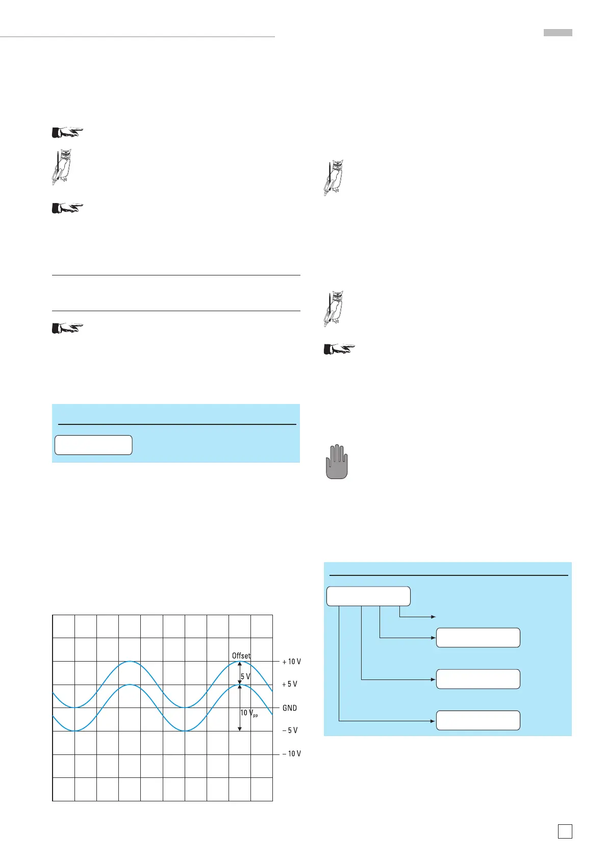
The picture shows 2 signals. The lower curve without offset with
10 V
pp
. Also shown are the limits of the output stage + and –10
Vp. The upper curve is offset by +5 V and reaxches the upper
limit of the output stage. Thus an increase of the offset e.g. to
6 V is impossible. Neither is it possible to increase the signal
amplitude as this would also go beyond +10 Vp.
If you decrease the offset to 4 V you can increase
HINT
the amplitude to 12 V
pp
.
The instrument will refuse the entry via the key-
board of any offset value larger than the maximum
allowed in the range selected. The former offset
value will remain valid, an error message will be
displayed. Neither will the menu pushbuttons
nor the knob allow entry of any offset larger than
permissible. This is also valid for the sweep func-
tion.
Using amplitude modulation the maximum voltage
is 10 V
pp
. Adding an offset here should be avoided,
however, if the amplitude is 8 V
pp
, an offset of ±2 V
STOP
may be added. The output is protected against
short-circuit or overload for about 30 sec. Over-load
means: extern voltage (AC + DC) >15 V or load < 50
ohms. In worst case the fi nal stage will be dama-
ged.
Sweep mode
The sweep mode is selected by pressing the button [SWP] in
. Parameters may be changed while in this mode, the output
will follow. If parameters should be chosen before selecting
the sweep mode, select the main menu 1 and go to ”Sweep“,
now you can set the parameters. By pushing [SWP] the sweep
SWP. (Sweep)
** SWEEP ACTIVE **
Start Stop Time Lin
SweepTime: 1.00 sec
- val + < cur >
Sp: 10.0000 kHz
- val + < cur >
St: 1.0000 kHz
- val + < cur >
Lin: "Select linear
or logarithmic"

 Loading...


