Trigger oscilloscope
EN
Tablet1000 User manual Copyright © Qingdao Hantek Electronics Co., LTD
42
9.5.3 Video trigger
Video triggers can be used to capture complex waveforms of most standard analog video
signals as well as HD video signals. The trigger circuit can detect the vertical and
horizontal intervals of the waveform and generates a trigger based on the selected video
trigger setting. This series of oscilloscopes supports NTSC (National Television Stands
Committee) and PAL.
1. Click the trigger area in the lower right corner of the screen to enter the Trigger
menu.
2. Click Video on the left side of the menu.
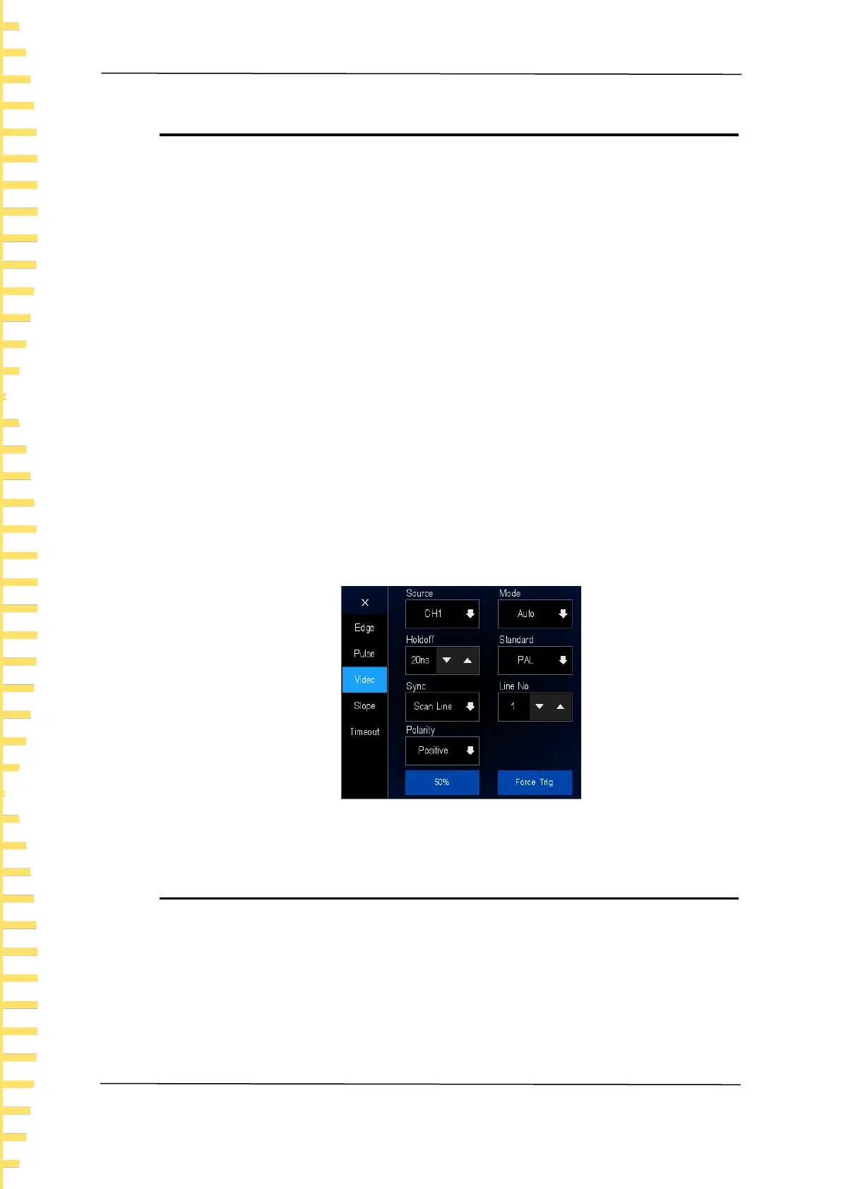
3. Click Source and select CH1 ~ CH4 as the trigger source.
4. Click Mode and select trigger mode (automatic, normal, single).
5. Click Holdoff to adjust the trigger hold-off.
6. Click Standard and select the desired video standard. This series of oscilloscopes
support video standards: NTSC, PAL, HDTV720p, HDTV1080p, HDTV1080i.
7. Click Sync, select the required field or line (scan line, line number, odd field, even
field, all fields) to trigger the signal.
8. Click Line No. to set the line number in the field to trigger.
9. Click Polarity and select the trigger polarity (positive and negative).
Positive: Triggered when a signal with positive polarity pulse width occurs.
Negative: Triggered when a signal with negative polarity pulse width occurs.
Figure 9.4 Video trigger menu
9.5.4 Slope trigger
Slope trigger sets the positive or negative slope trigger of the oscilloscope from one level
to another within a specified period of time.
As shown in the figure below, the time difference between the two points (A and B) where
the high and low trigger levels intersect the rising (falling) edge of the waveform is
defined as the positive (negative) slope time.
 Loading...