17
Before start Installation Operation
Screen block diagram
Operating screen
Configuration screen
Specifications
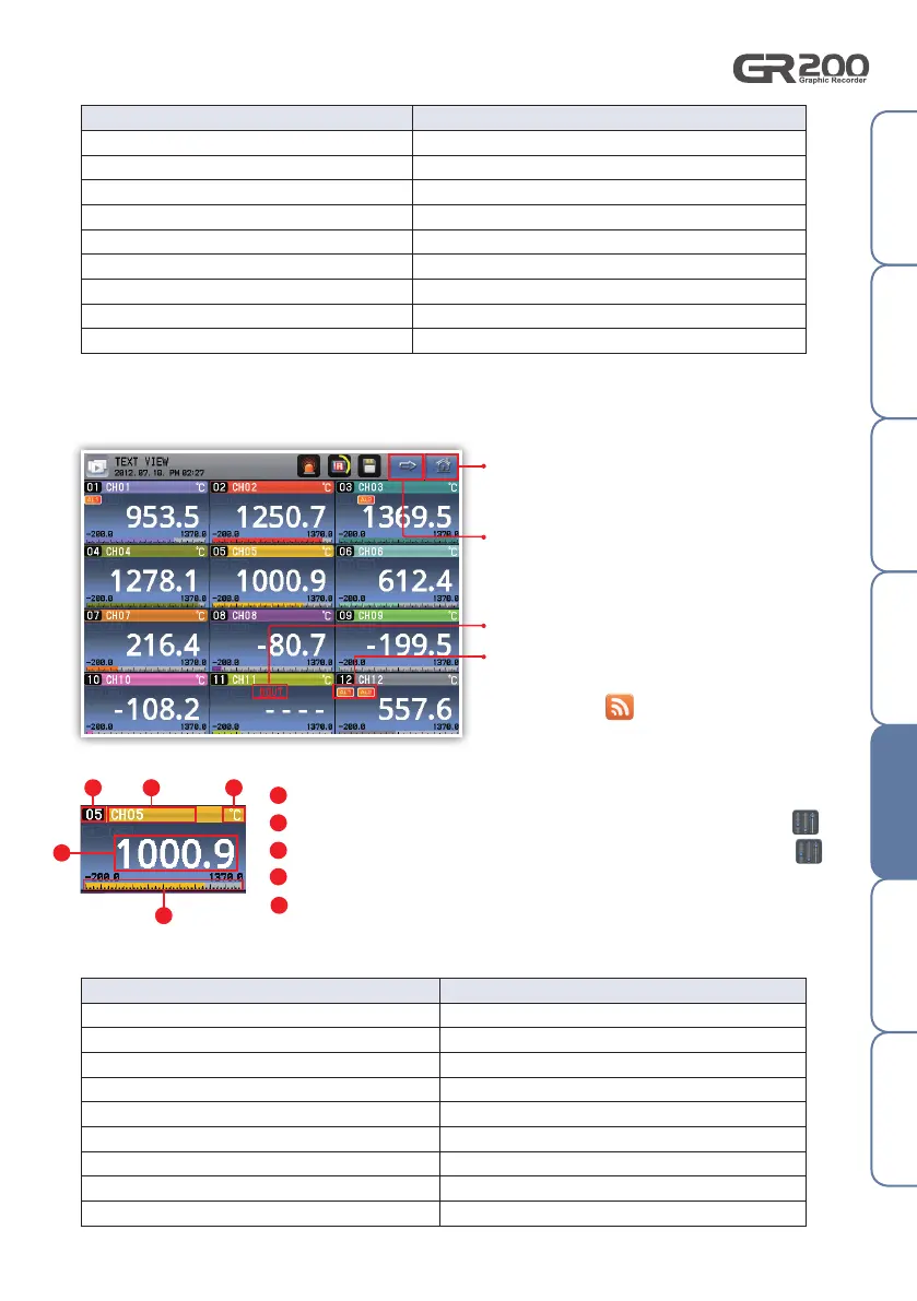
5. Digital screen
It is the screen which displays the channel measurement with numbers.
Fig. 23) Digital screen
Go to the menu screen.
Go to the bar graph screen.
Display the measured value.
Display the channel number.
Display the channel name. The channel name may be edited in the "Channel configuration ".
Display the channel unit. The displayed unit may be configured in the "Channel configuration ".
Check the measurement level within the display range as the grid.
The character appears when the alarm is
activated. The alarm types may be configured
in "Alarm and DI ".
Errors occurred Display
I/O connection error
"I/O CONNECTION ERROR" blinks on the screen name
Input connection error Display "----"
AD error
Display "----"
Correction error Display "----"
Calculation error Display "----"
User BURN OUT error Display "----"
BURN OUT error Display "----"
RJC error Alternatively display "RJC" and the measured value
Out of the measurement range (-5 ~ 0 %, 100 ~ 105 %)
Alternatively display "----" and the measured value
[ Display the error on the trend screen ]
Errors occurred Display
I/O connection error
"I/O CONNECTION ERROR" blinks on the screen name
Input connection error "----" displays and "CONNECT ERR" blinks
AD error "----" displays and "ADC" blinks
Correction error "----" displays and "CAL" blinks
Calculation error "----" displays and "CALC" blinks
User BURN OUT error "----" displays and "USER BOUT" blinks
BURN OUT error "----" displays and "BOUT" blinks
RJC error The measured value displays and "RJC" blinks
Out of the measurement range (-5 ~ 0 %, 100 ~ 105%)
Display the measured value and "OVER" blinks
[ Display the error on the digital screen ]
Display the error from the channel.
1
1
2
2
3
3
4
4
5
5
 Loading...