WIRING
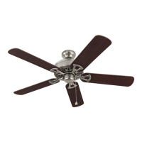
Wrap electrical tape around each individual wire
connector (CC) down to the wire as shown in Fig. 2.
WARNING: Make sure no bare wire or wire
strands are visible after making connections. Place
green and white connections on opposite side of box
from the black and blue (if applicable) connections.
Turn spliced/taped wires upward and gently push
wires and wire connectors (CC) into outlet box.
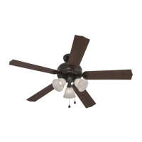
IMPORTANT: Using a full range dimmer switch to
control fan speed will cause a loud humming noise
from fan. To reduce the risk of fire or electrical
shock, do NOT use a full range dimmer switch to
control fan speed. (Fig. 3)
CC
CC
2
CC
CC
E3 Wire Connector x4
3
1
2
3
Dimmer
Switch
Speed
Switch
For illustrative purposes only--not
intended to cover all types of controls
FINAL INSTALLATION
9
2.
Hardware Used
3.
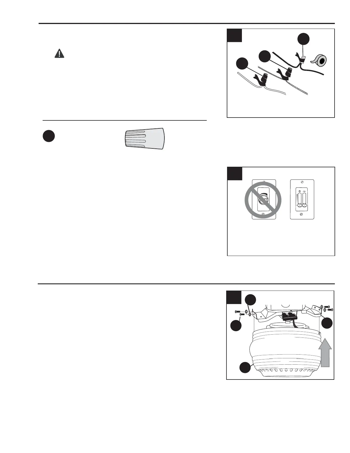
Temporarily raise motor housing (B) to mounting
bracket (A) to determine which two mounting bracket
screws (R) align with slotted holes in motor housing
(B) and partially loosen these two mounting bracket
screws (R). Remove the other two mounting bracket
screws (R) and star washers (S). Now, lift motor
housing (B) to mounting bracket (A) again, aligning
slotted holes in motor housing (B) with loosened
mounting bracket screws (R) in mounting bracket (A).
Twist motor housing (B) to lock. Re-insert mounting
bracket screws (R), along with star washers (S), that
were previously removed. Tighten all four mounting
bracket screws (R) securely. (Fig. 1)
1.
A
S
2
B
R
 Loading...