Signal description M24Cxx-W, M24Cxx-R, M24Cxx-F
10/34
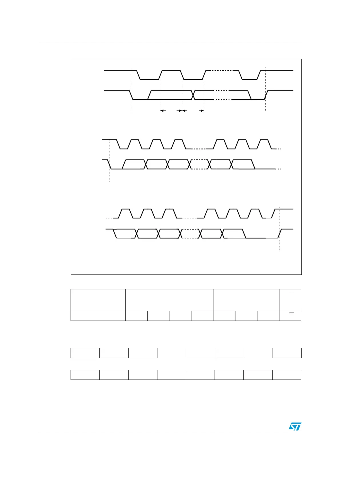
Figure 5. I
2
C bus protocol
Table 2. Device select code
Device Type Identifier
(1)
1. The most significant bit, b7, is sent first.
Chip Enable Address
(2)
2. E0, E1 and E2 are compared against the respective external pins on the memory device.
RW
b7 b6 b5 b4 b3 b2 b1 b0
Device Select Code 1 0 1 0 E2 E1 E0 RW
Table 3. Address Most Significant Byte
b15 b14 b13 b12 b11 b10 b9 b8
Table 4. Address Least Significant Byte
b7 b6 b5 b4 b3 b2 b1 b0
SCL
SDA
SCL
SDA
SDA
START
Condition
SDA
Input
SDA
Change
AI00792B
STOP
Condition
1 23 7 89
MSB
ACK
START
Condition
SCL
1 23 7 89
MSB ACK
STOP
Condition
Harman Kardon
VR 151 Service Manual
Page 104 of 131
 Loading...