EML3418
Elite Semiconductor Memory Technology Inc./Elite Micropower Inc. Publication Date: Jan. 2011
Revision: 2.3 3/17
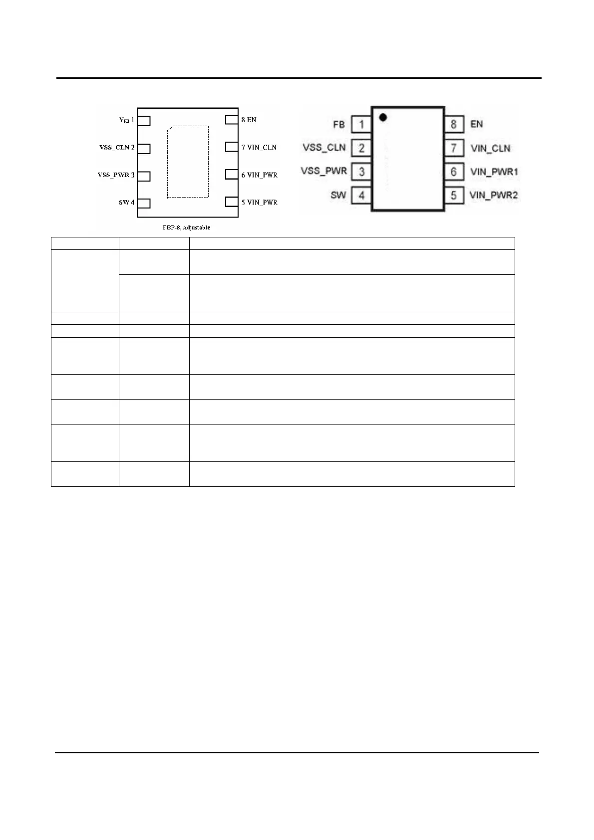
Package Configuration
ʳ ʳ ʳ ʳ ʳ ʳ ʳ ʳ ʳ ʳ ʳ ʳ ʳ ʳ ʳ ʳ ʳ ʳ ʳ ʳ ʳ ʳ ʳ ʳ ʳ ʳ ʳ
SOP-8 Adjustable
Pin Functions
Pin # Pin Name Function
V
FB
(Adjustable)
Feedback Pin. Receives the feedback voltage from an external
resistive divider across the output.
1
V
OUT
(Fixed
voltage)
Output Voltage Pin. An internal resistive divider divides the output
voltage down for comparison to the internal reference voltage.
2 VSS_CLN Analog Ground Pin.
3 VSS_PWR Power Ground Pin.
4 SW
Switch Pin. Must be connected to Inductor. This pin connects to
the drains of the internal main and synchronous power MOSFET
switches.
5, 6 V
IN_PWR
Power Input Pin. Must be closely decoupled to GND pin with a
4.7ǍF or greater ceramic capacitor.
7 V
IN_CLN
Analog Input Pin. Must be closely decoupled to GND pin with a
4.7ǍF or greater ceramic capacitor.
8 EN
Enable Pin. Minimum 1.2V to enable the device. Maximum 0.4V
to shut down the device. Do not leave this pin floating and
enable the chip after Vin is in the input voltage range.
Exposed
pad
Connect to Ground.
Harman Kardon
VR 151 Service Manual
Page 54 of 131
 Loading...