DB1230
Preliminary Datasheet DB1230P-02
19. Oct. 2011
2 of 19
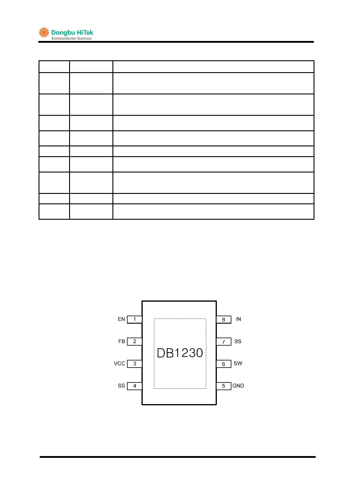
PIN DESCRIPTION
PIN NO. SYMBOL DESCRIPTION
1 EN
Enable pin.
For automatic start-up, please leave it open and in case of on/off control, there
should be pull-down resistor.(10K~100Kohm)
2 FB
Feedback pin.
External resistors are connected between OUT and GND to set the regulated
output voltage based on 0.8V reference.
3 VCC
Internal regulated output.
A decoupling capacitor should be close to this pin as possible
4 SS
External soft-start program pin.
An external capacitor should be connected to GND.
5 GND Ground.
6 SW
Switching Node.
An inductor, internal high-side and low-side power switches are connected
7 BS
Bootstrap pin.
The bootstrap charge capacitor should be connected between BS and SW to
provide a supply to gate driver of high-side power switch.
8 IN Input power supply pin.
EP Exposed Pad
Exposed pad. Connect the exposed pad to GND for heat sink.
This pin combines thermal sink and power ground.
PIN CONFIGURATION
TOP VIEW
G
8-SOP-EP Package
Fig.3 DB1230 PIN configuration
Harman Kardon
VR 151 Service Manual
Page 59 of 131
 Loading...