ADI Confidential ADV7623
Rev. Sp0 | Page 11 of 16
Pin No. Mnemonic Type Description
56 TX2− HDMI output
Differential Output Channel 2 Complement. Differential output of the red data at 10×
the pixel clock rate; supports TMDS logic level.
57 TX2+ HDMI output
Differential Output Channel 2 True. Differential output of the red data at 10× the pixel
clock rate; supports TMDS logic level.
58 TXGND Ground TXAVDD Ground.
59 CEC Digital I/O Consumer Electronics Control Channel (5 V Tolerant).
60 DGND Ground DVDD Ground.
61 DVDD Power Digital Supply Voltage (1.8 V).
62 ALSB Digital input This pin is used to set the I
2
C address of the Rx IO and the Tx main map.
63
CS
Digital input
Chip Select Pin. This pin must be set low or left floating for the chip to process I
2
C messages
that are destined for the ADV7623. The ADV7623 ignores I
2
C messages that it receives if
this pin is high.
64 EP_SCK Digital output SPI Clock Interface for the EDID/OSD.
65 EP_CS Digital output SPI Chip Selected Interface for the EDID/OSD.
66 EP_MOSI Digital output SPI Master Out/Slave In for the EDID/OSD.
67 EP_MISO Digital input SPI Master In/Slave Out for the EDID/OSD.
68 MCLK_IN Digital input
Audio Reference Clock. 128 × N × f
S
with N = 1, 2, 3, or 4. Set to 128 × sampling frequency (f
S
),
256 × f
S
, 384 × f
S
, or 512 × f
S
. It supports CMOS logic levels from 1.8 V to 3.3 V.
69 SCLK_IN Digital input I
2
S Audio Clock. It supports CMOS logic levels from 1.8 V to 3.3 V.
70 AP5_IN Digital input Audio Input Port 5. It supports CMOS logic levels from 1.8 V to 3.3 V.
71 AP4_IN Digital input Audio Input Port 4. It supports CMOS logic levels from 1.8 V to 3.3 V.
72 DGNDIO Ground DVDDIO Ground.
73 DVDDIO Power Digital I/O Supply Voltage (3.3 V).
74 AP3_IN Digital input Audio Input Port 3. It supports CMOS logic levels from 1.8 V to 3.3 V.
75 AP2_IN Digital input Audio Input Port 2. It supports CMOS logic levels from 1.8 V to 3.3 V.
76 AP1_IN Digital input Audio Input Port 1. It supports CMOS logic levels from 1.8 V to 3.3 V.
77 AP0_IN Digital input Audio Input Port 0. It supports CMOS logic levels from 1.8 V to 3.3 V.
78 SDATA Digital I/O I
2
C Port Serial Data Input/Output Pin. SDATA is the data line for the control port.
79 SCL Digital input I
2
C Port Serial Clock Input. SCL is the clock line for the control port.
80 DGND Ground DVDD Ground.
81 DVDD Power Digital Supply Voltage (1.8 V).
82
INT1
(AMUTE1)
Digital output
Interrupt Pin. This pin can be active low or active high. When status bits change, this pin is
triggered. The events that trigger an interrupt are under user control. This pin can also output
an audio mute signal.
83
INT2
(AMUTE2)
Digital output
Interrupt Pin. This pin can be active low or active high. When status bits change, this pin is
triggered. The events that trigger an interrupt are under user control. This pin can also output
an audio mute signal.
84 INT_TX Digital output Interrupt; Open Drain. A 2 kΩ pull-up resistor to the microcontroller I/O supply is recommended.
85 DGNDIO Ground DVDDIO Ground.
86 DVDDIO Power Digital I/O Supply Voltage (3.3 V).
87 AP0_OUT Digital output Audio Output Port 0.
88 AP1_OUT Digital output Audio Output Port 1.
89 AP2_OUT Digital output Audio Output Port 2.
90 AP3_OUT Digital output Audio Output Port 3.
91 AP4_OUT Digital output Audio Output Port 4.
92 DGND Ground DVDD Ground.
93 DVDD Power Digital Supply Voltage (1.8 V).
94 AP5_OUT Digital output Audio Output Port 5.
95 SCLK_OUT Digital output Audio Serial Clock Output.
96 MCLK_OUT Digital output Audio Master Clock Output.
97
RESET
Digital input
System Reset Input. Active low. A minimum low reset pulse width of 5 ms is required to reset
the ADV7623 circuitry.
98
PWRDN
Digital input
Active Low Power-Down Pin. If used, this pin should be pulled high to power up the
ADV7623. This pin can also be used as an in system power detect where internal EDID can
be powered from a 5 V signal of the HDMI port when it is connected to active equipment.
t supports CMt supports CM
2. It supports CMt supports
t 1. It supports C 1. It suppor
ort 0. It support0. It supp
rupt Pin. This pipt Pin. This
ggered. The evened. The e
n audio mute sigudio mute
triggered. Theriggered. T
ogic levels froogic levels fro
A is the dataA is the dat
he clock line for thclock line for th
active low or active low or acti
trigger an interrupr an interru
an be active low oe active low
that trigger an interigger an in
ain. A 2 kΩ pullain. A 2 kΩ pull
ply Voltage (3.3 V)y Voltage (3.3 V)
Output Port 3. utput Port 3
o Output Port 4. Output Port 4.
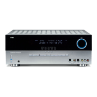
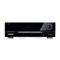
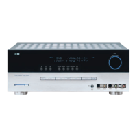
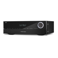
Harman Kardon
VR 151 Service Manual
Page 73 of 131
 Loading...