TEC0020 2018JAN3 P/N: 630-00025 Rev D AL600 & AL690 Hybrid Installation & Owner's Manual
19
Installation - AL600
SECTION 2 : INSTALLER
With Folding 3rd Row Seating
Figure 19-1
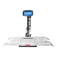
9. The AL600’s leg will need to be mounted
between 32” and 42” from the internal surface of the
closed back door of the vehicle.
Examine the oor for additional seat attachment
points recessed into the oor. [Figure 19-2]
32”
32”
42”
42”
CENTER
2ndROW SEAT ING
2nd ROW SEAT ING
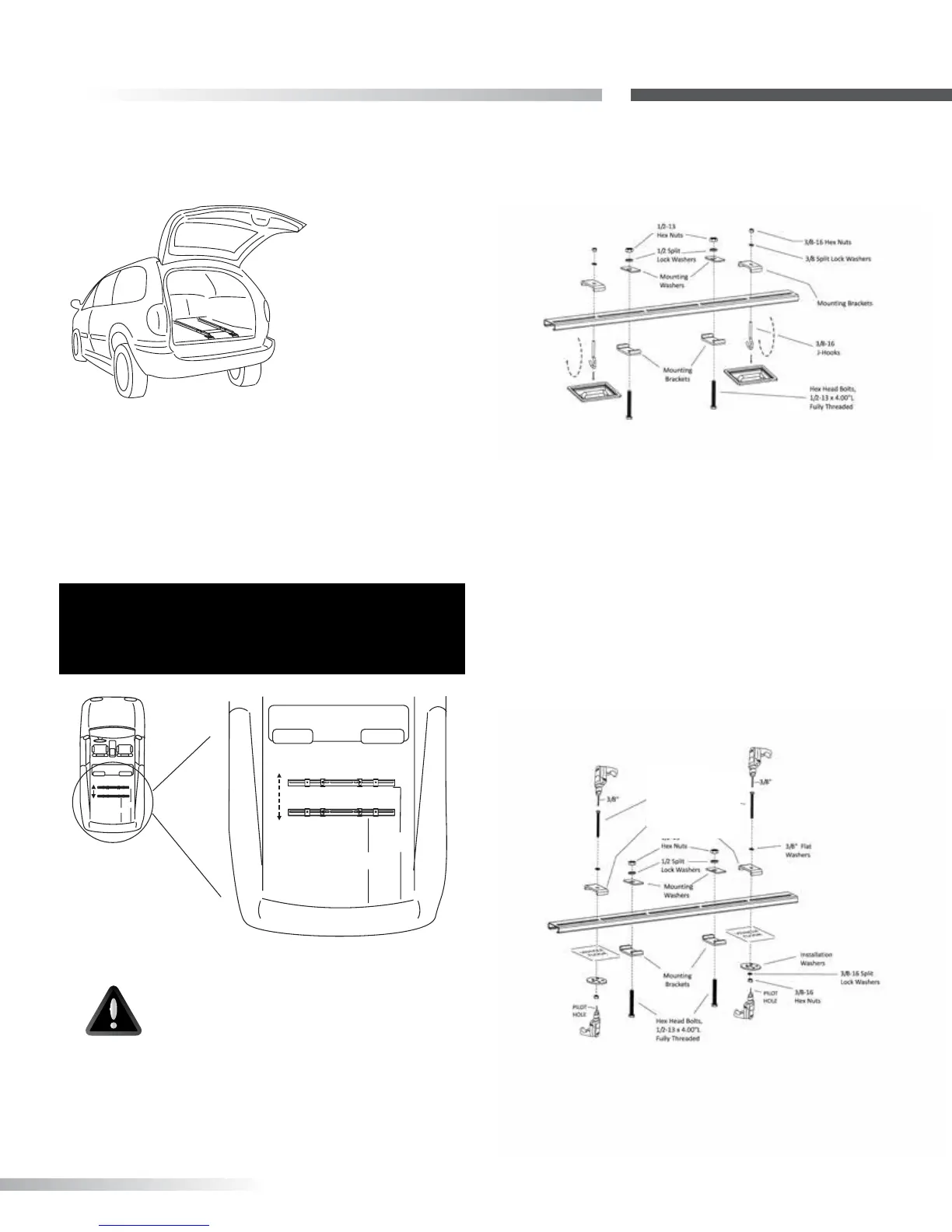
10 A. If Seat Attachment Points ARE Available: See
Figure 19-3 for mounting diagram.
Figure 19-2
Figure 19-3
10 B. If Seat Attachment Points are NOT Available:
Look under vehicle in approximate area where Leg will
need to be mounted.
Drill a pilot hole rst, up from under the vehicle to
ensure nothing will be damaged. [Figure 19-3]
Find hole from inside vehicle and drill 3/8” hole down
through vehicle’s oor. [Figure 19-4]
Figure 19-4
CAUTION
USE EXTREME CAUTION
Avoid Gas Tank, Fuel / Brake /
Electrical Lines
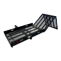
8. With BA-02 installed in rear cargo area, examine
oor for area to install leg assembly. [Figure 19-1]
IMPORTANT:
Attachment Points MUST be FLUSH or LOWER than
the oor.
Hex Head Bolt,
3/8-16 x 4.00" L
Fully Threaded