4 HFS6801+ Installation and Operation Manual
Chapter 1: Introduction
Module Descriptions
Front Module
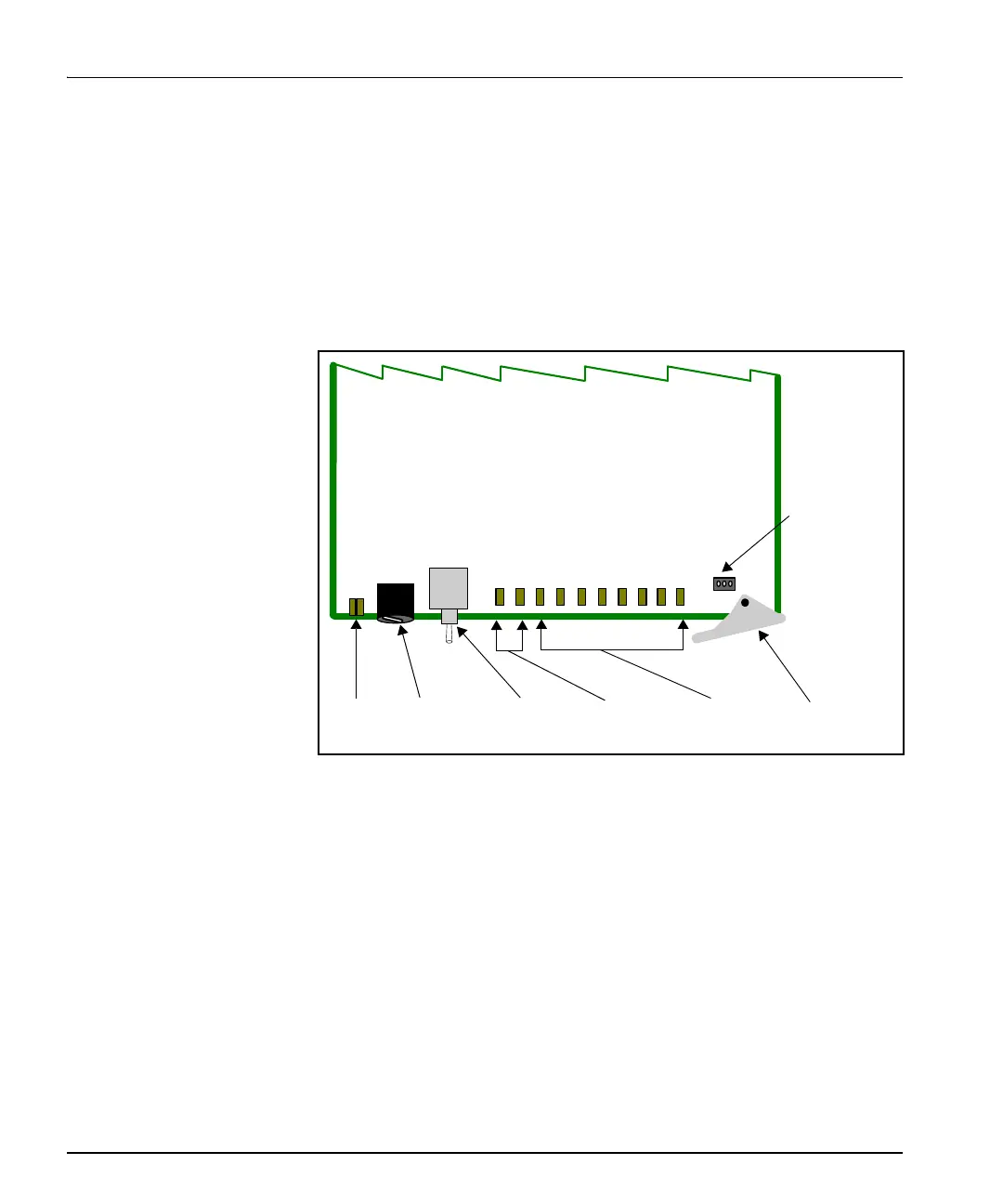
Figure 1-1 is a generic top-front view of a typical 6800+ module and
shows the general location of standard LEDs, controls, and jumpers.
The number of Control and Monitoring LEDs on 6800+ modules
varies.
Figure 1-1. Typical 6800+ Module
Table 1-1 on page 5 briefly describes generic 6800+ LEDs, switches,
and jumpers. See “Chapter 3: Operation” for more information on
specific HFS6801+ module controls, LEDs, and jumpers.
Module
status
LEDs
Mode select
rotary
switch
Navigation
toggle
switch
Monitoring
LEDs
Remote/local
control
jumper
Extractor
handle
Control
LEDs