16
6.4 Fence
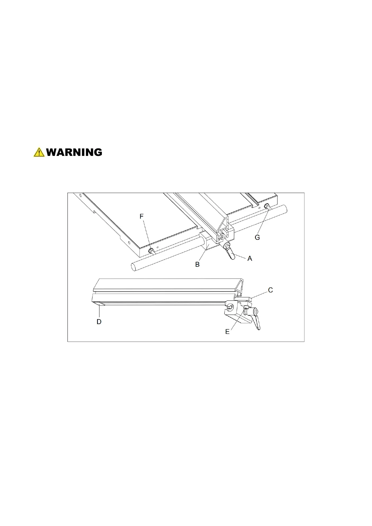
6.4.1 Fence Plate Positions (Refer to Figure 15.)
1. Loosen the fence plate locking screws (E) on the left side of the fence guide (B), until the
lock bar (C) protrudes enough to slide the aluminum fence plate out of the fence guide
(B).
2. Uninstall the fence plate rear support by sliding out the vane (D).
3. With the fence plate facing down, install the support and tighten it.
4. Position the fence plate where needed and slide it back to the fence guide.
5. Re-tighten the locking handle.
The aluminum fence plate can be installed in two positions; vertically or horizontally.
The horizontal position is useful for smaller workpieces. (The zero setting of the
cursor cannot be used with the horizontal fence position.)
Fig. 15
6.4.2 Setting the Fence to the Table Clearance
Refer to figure 15.
1. Check the clearance between the table and the bottom of the fence. The fence should
not rub against the table surface but be slightly above it. This clearance should be the
same at the front or rear of the table.
2. If the clearance is not the same, use a combination of the following two adjustments:
With the provided hex wrench, loosen the locking nuts (F) and then rotate the two fence
square adjustment screws (G) the same amount to raise or lower the fence body from
the guide rail. Clockwise raises the fence plate and counterclockwise lowers the fence
plate, when the fence-to-table clearance is equal, re-tighten the locking nut against the
fence plate.