23
Sultan 234 Series
Admittance Smart Switch Series
Manual
Rev 1.2, June 2008
SETUP PROCEDURE
REMOTE VERSION
1. Mount the unit in its actual position. (see mounting procedure - page 9-10)
Make sure that external ground wire is connected between the outside ground screw on the Gladi-
ator housing and the roof/wall/side of the silo/tank/vessel/chute. (For non metallic tanks make sure
that external ground wire is connected between the same outside ground screw on the housing
and the general plant ground potential.)
2. Check where the actual level is relative to the probe.
Make sure that product is not touching the probe - ideally it needs to be > 500mm away.
(If the silo/vessel/tank/chute is very small you must ensure that the material is as far away as pos-
sible - it must not be touching the probe).
3. Turn the power on
The display will turn on and the failsafe relay will switch. The display will scroll through the follow-
ing messages: Hawk, Amp SerialNo, Type, Amp Soft Ver, Device ID, SensorSerial, SensorModel,
Sens SoftVer, Sensor Addrs, Gladiator System Amp.
The unit will then go into operational mode displaying ‘Switch’ with a % value. This % value repre-
sents the changing admittance reading.
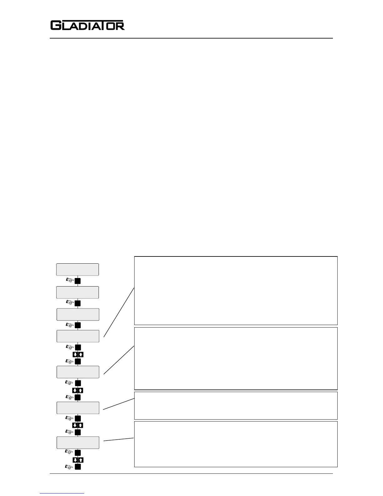
4. Simple “1-minute” Setup - Follow the ow chart
Select the Switch point (sensitivity)
The output relay will switch at the entered % value. The default value of
50% will be suitable for detecting most media. For detection of products
having low dieletric constant, select a lower % value and vice versa. A
higher % value will require the product to come nearer to the probe or
cover more of the probe before switching will occur. When the level falls
the relay will switch back at half of the entered switch point % value.
Select the Time Delay
Set the time to be used for both switch on and switch off delays
(default: 0.1 seconds). Maximum Delay is 40 seconds.
Cancel Inuence of Mounting and/or Buildup
Do not proceed with this step unless the product is not touching the
probe. Ideally it needs to be > 500mm away.
Select ‘Yes’ to start the mounting calibration. ‘Wait’ will be dis-
played during the calibration for up to 30 seconds.
Unit is now able to cancel the inuence of the mounting and/or
build-up. The % reading has been zeroed with the existing process
conditions and probe history log has been cleared.
Select the required relay action
The Relay can switch ‘ON’ or ‘OFF’ as the product approaches the
probe and switch ‘ON’ or ‘OFF’ in response to an instrument failure.
For details see page 14. Set the parameter to FailSafe Low or
FailSafe Hi depending on your requirements.