44 USE ONLY GENUINE REPLACEMENT PARTS
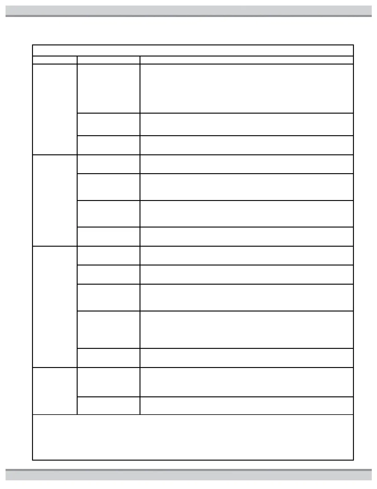
Table17: Troubleshooting Lookup Chart
Suggested Troubleshooting Action
No code
displayed
Open FC1
and/or FC2
Fuses.
1. Verify that
120VAC Voltage
Selector Plug is not
installed with a
240VAC field power
supply.
Check that proper Voltage Selector Plug is installed. If OK, proceed to step
2.If 120VAC plug is installed and field supply voltage is 240VAC, FC1 and
FC2 fuses may be blown. Install the correct Voltage Selector Plug and new
FC1 and FC2 fuses.
2. Check for faulty
Transformer wiring.
Inspect Transformer wiring. Ensure insulation on wiring is not worn. If OK,
proceed to step 3.
No code
displayed
Open FC3
and/or F1
Fuses
1. Check for faulty
Gas Valve wiring.
Inspect Gas Valve wiring. Ensure insulation on wiring is not worn. If OK,
proceed to step 2.
2. Verify that Gas
Valve is not
defective.
Measure for resistance across Gas Valve terminals and between each
terminal and ground. If short exists, replace Gas Valve. If OK, proceed to
step 3.
3. Check for faulty
ignition control
board wiring.
Inspect ignition control board wiring is to supplied wiring diagram. Ensure
insulation on wiring is not worn and no bare wire is exposed. If OK proceed
to step 4.
4. Ignition control
board is defective.
Replace ignition control board.
No code
displayed
Open FC4
Fuse.
1. Check for faulty
Igniter wiring.
Inspect Igniter wiring. Ensure insulation on wiring is not worn. If OK,
proceed to step 2.
2. Check for faulty
Blower wiring.
Inspect Blower wiring. Ensure insulation on wiring is not worn. If OK,
proceed to step 3.
3. Check for
defective Igniter.
Disconnect Igniter plug from ignition control board. Measure resistance
across Igniter. Resistance should be 10.9-19.7 ohms at 77°F. If out of this
range, replace igniter. If OK, proceed to step 4
4. Check for
defective Blower.
Disconnect Blower plug from ignition control board. Measure resistance
across Blower windings. Winding resistance across lead should be in the
following range: Red-to-White: 4 to 5 ohms. If measured values vary
substantially from these values, blower is defective. Replace. Otherwise
proceed to step 5.
5. Ignition control
board is defective.
Replace ignition control board.
AC
displayed
Air switch
circuit closed
error
1. Check for
defective blower on
relay or ignition
control board.
Disconnect Blower plug from ignition control board. With heater off,
measure continuity across pins 1 and 2 of receptacle on ignition control
board. If closed, ignition control board relay is defective. Replace ignition
control board. If OK, proceed to step 2.
2. Vacuum switch is
defective.
Replace blower vacuum switch.