USE ONLY GENUINE REPLACEMENT PARTS 45
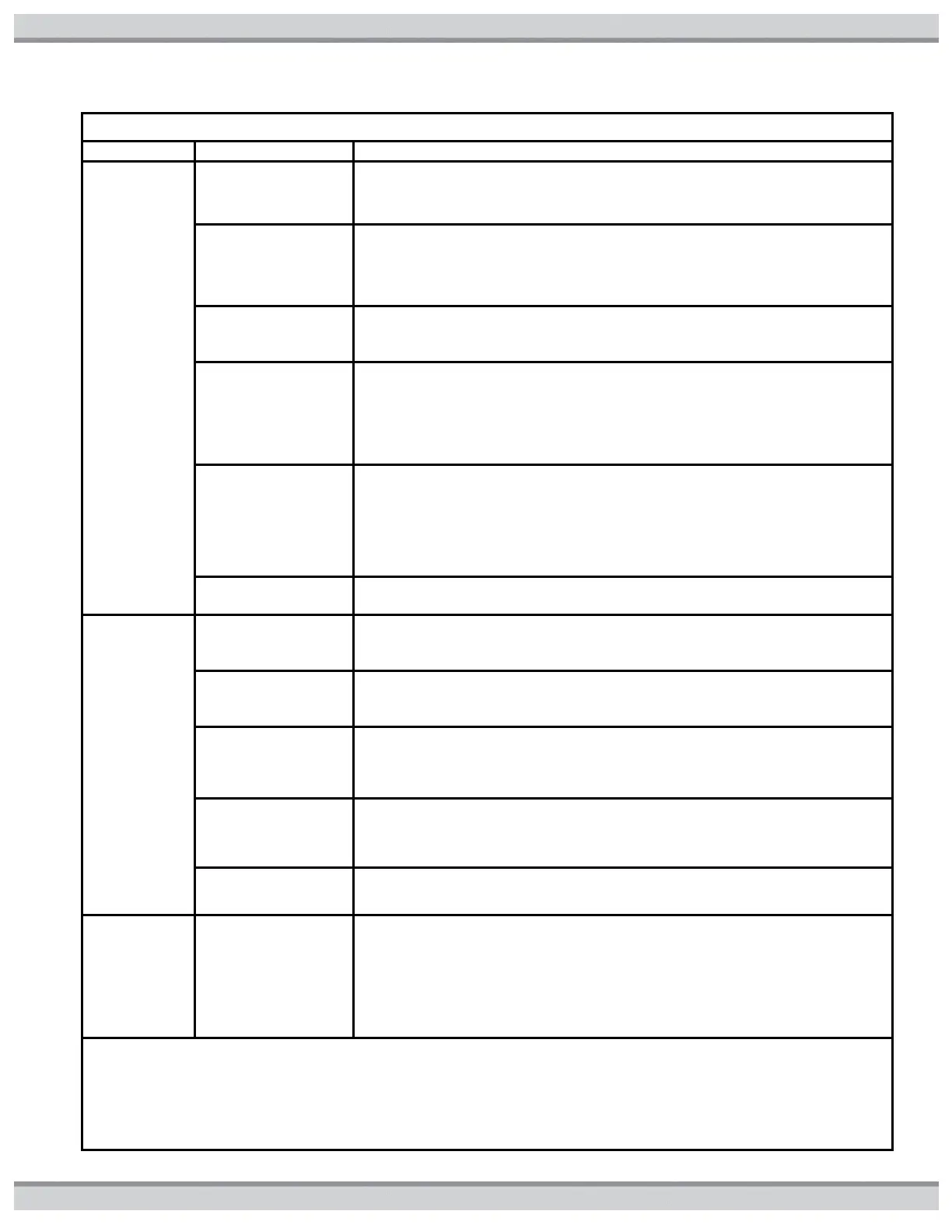
Table17: Troubleshooting Lookup Chart
Suggested Troubleshooting Action
AO
displayed
Air switch
circuit open
error
1. Check for faulty
vacuum switch
tubing
Check tubing and replace if necessary. If OK, proceed to step 2.
2. Check for faulty
vacuum switch
wiring or
connection.
Inspect vacuum switch wiring. Ensure wire harness terminals are securely
fastened to spade terminals on vacuum switch. If OK, proceed to step 3.
3. Check for faulty
blower wiring or
connection
Inspect blower wiring. Ensure plug on blower is securely fastened to
ignition control board. If OK, proceed to step 4.
4. Check for
defective vacuum
switch
Disconnect Blower plug from ignition control board. Measure resistance
across Blower windings. Winding resistance across lead should be in the
following range; Red-to-White: 4 to 5 ohms. If measured values vary
substantially from these values, Blower is defective. Replace. If OK,
proceed to step 5.
5. Check for
defective blower
relay.
Disconnect Blower plug from ignition control board. Place heater in Pool or
Spa Mode. Lower set point temperature to generate call for heat. During
pre-purge period, measure for 120VAC across pins 1 and 2.If 120VAC is
not present, ignition control board relay is defective. Replace ignition
control board. If OK, proceed to step 6
6. Vacuum switch is
defective
Replace blower vacuum switch.
bd
displayed
Ignition
control board
data error
1. Verify that FC4
Fuse on Fuse
Board is not open.
Remove FC from fuse holder. Measure continuity across fuse. If OK,
reinstall fuse and proceed to step 2. If Fuse is open, proceed to section
titled ‘‘Open FC4 Fuse’’.
2. Verify high
voltage output from
Fuse Board.
Disconnect plug from P6 connector of Fuse Board. Measure for120VAC
across pins 3 and 5 of P6 receptacle on Fuse Board. If OK, reconnect plug
and proceed to step 3. If not OK, go to step 4.
3. Check for
defective Harness.
Disconnect plug from E10 connector of ignition control board. Measure for
120VAC across pins 1 and 3 of Plug on Harness. If OK, replace ignition
control board. If not OK, replace Harness.
4. Check for
defective
Transformer.
Disconnect plug from P4 connector of Fuse Board. Measure for120VAC
between pins 4 and 6 of plug from Transformer. If OK, proceed to step 5.
If not OK, replace Transformer.
5. Fuse Board is
defective
bo
displayed
Bypass
Operation
1. Check to see if
Ignition control
board is in Bypass
Operation
This is normal display when heater is being controlled by a remote
thermostat. No service is required. If heater is not being controlled by
remote thermostat, change setting by using the MODE key to put the
heater into STANDBY. Press and hold the DOWN key and then press and
hold the MODE key. Hold down both keys for 3 seconds until the indication
‘‘bO’’ is removed from the display.