46 USE ONLY GENUINE REPLACEMENT PARTS
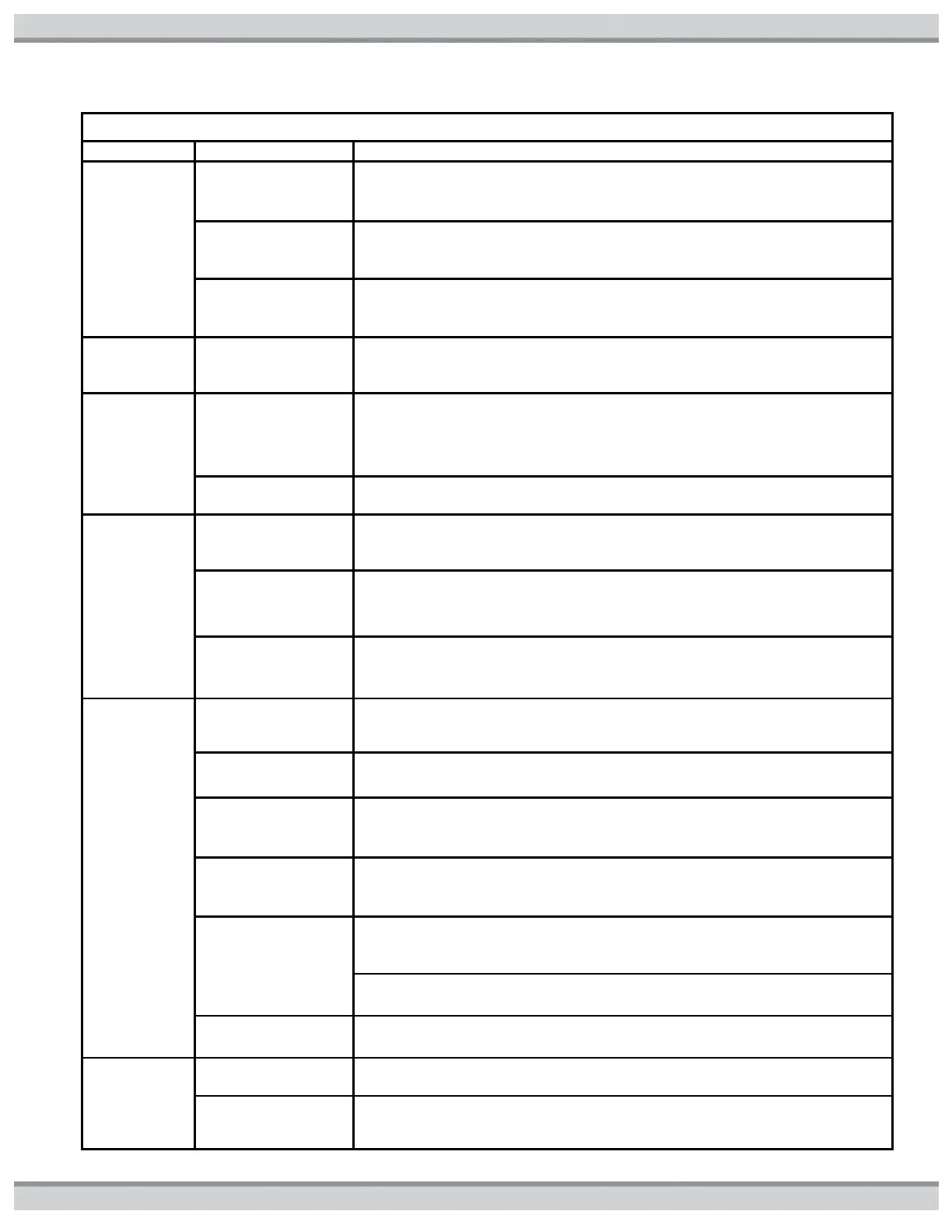
Table17: Troubleshooting Lookup Chart
Suggested Troubleshooting Action
CE
displayed
Control to
display
communica-
tion error
1. Disconnect and
then re- connect
power to heater.
Reset communication between Display Interface and Ignition control board
2. Check for faulty
wiring or
connection.
Inspect Display Interface Wiring. Ensure Display Interface Plug is securely
attached to ignition control board. If OK, proceed to step 3.
3. Display Interface
and/or Ignition control
board are defective.
Replace Display Interface and/or ignition control board
1. EEPROM error
Defective ignition
control board
Replace ignition control board.
HF
displayed
High flame
sensor signal
error
1. ignition control
board is defective
Using the sight glass, check to see if the flame is present in the unit. If not,
replace ignition control board. If flame is present, use a voltmeter to
determine if 24 VAC is present at the gas valve connections. If so, replace
ignition control board. If not, move to step2.
2. Gas Valve is
defective
HS
displayed
High temp.
sensing Error
1. Check remote
thermostat setting
Verify set point setting of remote thermostat is at or below 104°F. If set
point of remote thermostat is OK, or if heater is not configured for remote
thermostat, proceed to step 2.
2. Verify that the
water flow is
adequate
Verify that water flow to heater is above minimum required (see
SPECIFICATION in Getting Started Section). Note that intermittent periods
of low water flow will cause this error. If OK, proceed to step 3.
3. Check inlet water
temperature sensor
Compare the heater's temperature reading to the pool water temperature
with an accurate thermometer. If significantly different, replace inlet water
temperature sensor.
IF
displayed
Ignition
failure error
1. Ensure gas
supply shut off
valves are open.
Ensure that main gas shutoff installed adjacent to heater is open. Ensure
that knob on gas valve inside unit is in ‘‘on’’ position. If OK, proceed to step
2.
2. Check for low
gas supply press.
Ensure inlet gas supply pressure is between the minimum and maximum
values indicated on rating plate. If OK, proceed to step 3.
3. Check for faulty
flame sense
connection.
Inspect flame sense wiring. Ensure wire harness terminals are securely
fastened to flame sense and to ignition control board. If OK, proceed to
step 4.
4. Check for faulty
gas valve
connection
Inspect gas valve wiring. Ensure wire harness terminals are securely
fastened to spade terminals on gas valve. If OK, proceed to step 5.
5. Check for gas
valve failure or gas
valve relay failure.
1. Measure voltage across gas valve during trial for ignition. If 24VAC is
present and gas valve does not open, gas valve is defective. Replace gas
valve.
2. If 24VAC is not present, gas valve relay on ignition control board is
defective. Replace ignition control board.
Inspect gas orifices for blockages which could prevent gas flow. Remove
and inspect burners for blockages.
IO
displayed
Igniter open
error
1. Check for faulty
connection.
Inspect Igniter wiring. Ensure Igniter Plug is securely attached to ignition
control board. If OK, proceed to step 2.