13
T210
ELECTRICAL CONNECTION
Measuring cables should not be laid parallel to power cables and control circuits (that is,
not in shared cable ducts). If this is not possible, protect the measurement cable with a
rigid steel conduit, for example, and keep it as far away from other cables as possible.
Avoid stray fields from transformers, motors and contact switches.
Notice
At the maximum rotational speed of 30,000 rpm the cable length is limited to maximum
10 m.
5.4 Shielding design
The cable shield is connected in accordance with the Greenline concept. This encloses
the measurement system in a Faraday cage. It is important that the shield is laid flat on
the housing ground at both ends of the cable. Any electromagnetic interference active
here does not affect the measurement signal.
In the event of interference due to potential differences (compensating currents), discon
nect supply voltage zero from the housing ground at the measuring amplifier and lay a
potential equalization line between the transducer housing and the measuring amplifier
housing (copper cable, 10 mm
2
cable cross-section).
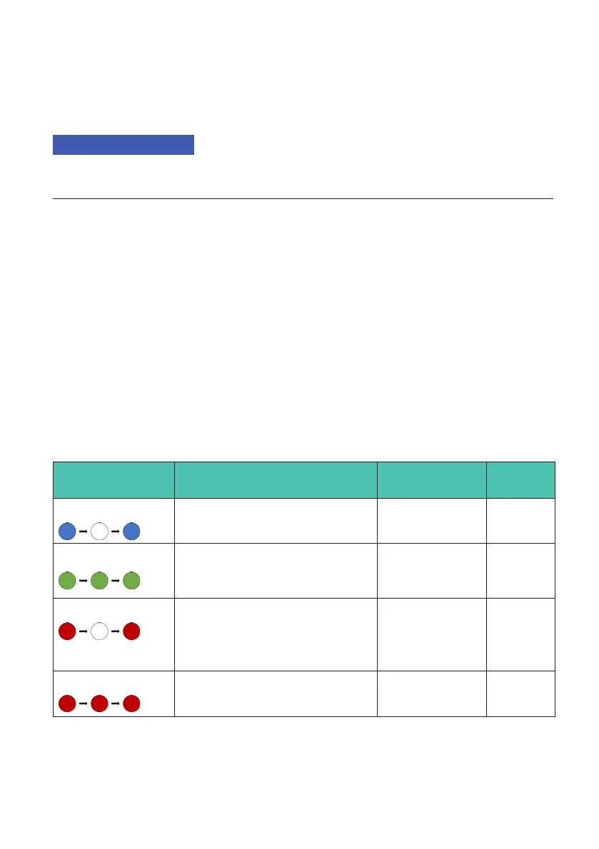
5.5 Status LED
The transducer has a status LED. The various states are shown in table Tab. 5.1.
LED Description Analog output
signals
Output
status
Flashing blue Boot-up
Measurement shaft is started.
-14 V and 0 Hz LOW
Lit green Ready for operation
Measurement shaft ready for
measurement.
Measurement
signal
HIGH
Flashing red Warning
Non-critical state. Technical spec
ifications are no longer guaran
teed.
Measurement
signal
LOW
Lit red Error
Critical state. Stop operation.
Error signal LOW
Tab. 5.1 Various LED states