T210
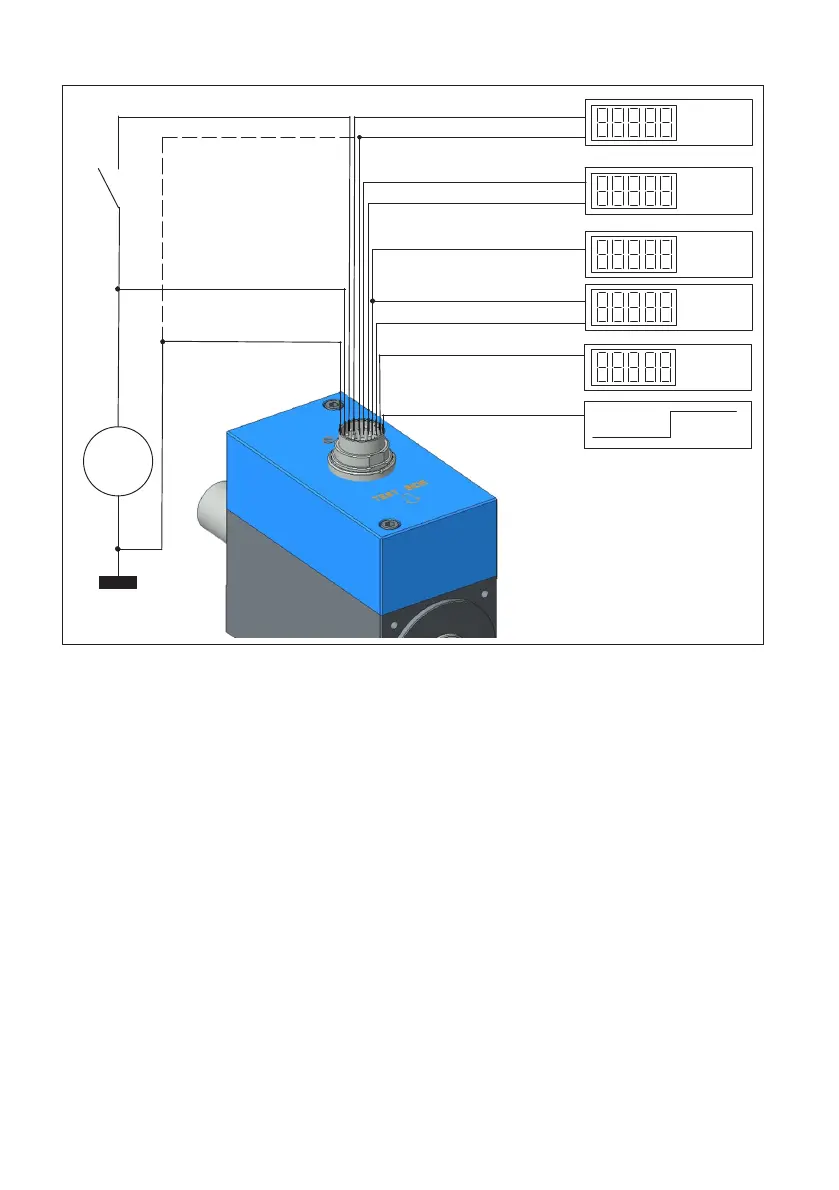
ELECTRICAL CONNECTION
12
low high
degr.
Angle of track B (pin G)
Angle of track A (pin B)
rpm
Rotational speed output
(pin B)
Nm
Frequency output (pin L)
Frequency output (pin A)
Nm
Torque ground (pin D)
Torque (pin C)
U=
Supply ground (pin E)
Supply (pin F)
Control (pin K)
The supply ground and
moment ground can
be combined at source
if required.
rpm
Reference signal Z (pin H)
Measurement signal -
ready for measurement
Fig. 5.1 Connection diagram T210
The transducer generates an internally electrically isolated measurement signal. The
grounds must not be bridged directly on the transducer, otherwise measurement errors
may occur depending on the supply and analysis device. If necessary they can be bridged
on the supply and analysis device. The "control signal" is used to test the transducer. It is
connected to the torque outputs at 50% of the nominal signal. The modulation level is
4.5 V up to the supply voltage. The reference voltage is the supply ground.
The transducer has a ready for measurement signal. If the output is returning a HIGH
level, normally the measurement electronics are working. With a LOW level there is an
error.
5.3 Extending the cable
Extension cables must be shielded and of low capacitance.
With cable extensions it is important to ensure that a good connection is provided, with
minimum contact resistance and good insulation. So all connections should be soldered,
or at least made with secure, stable clamp terminals or screwed plug connectors.