11
T210
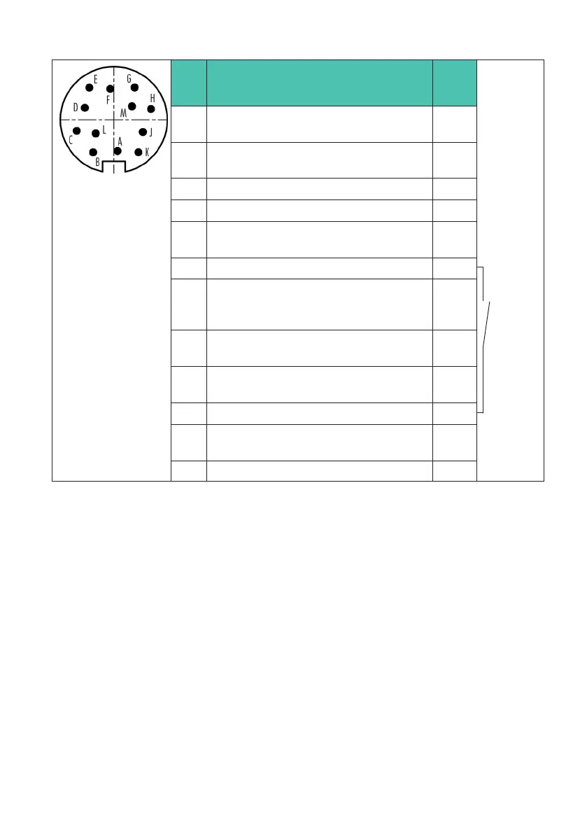
ELECTRICAL CONNECTION
Pin Assignment Wire
color
Trigger
control sig
nal (with
out VK20A)
Switch
(NO)
A Torque measurement signal (fre
quency output; 5 V)
1)
2)
bk
B Rotational speed/angle of rotation
measurement signal A; 5 V
rd
C Torque measurement signal ±10 V br
D Torque measurement signal 0 V wh
E Ground (supply+rotational speed/an
gle of rotation)
ye
F Supply voltage 10 V … 30 V vt
G Rotational speed/angle of rotation
measurement signal B; 5 V; lagging by
90°
gn
H Rotational speed reference signal Z;
5 V
pk
J Measurement signal - ready for mea
surement
gr
K Control signal triggering gy/pk
L Torque measurement signal (fre
quency output; 5V)
1),
2)
bl/rd
M Not in use bl
1)
Complementary signals RS-422. Problems with signal quality can be mitigated by a termination resistor
(R=120 Ohm) between the wires (bl) and (bl/rd).
2)
RS-422: Pin A corresponds to A, pin L corresponds to B