Electrical connections
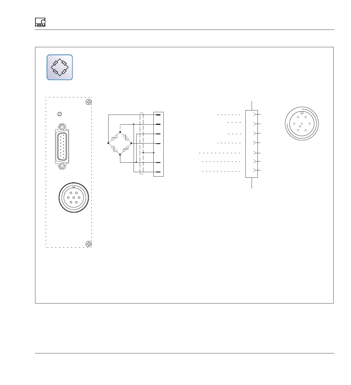
Transducer connection
DMP41 A03470_07_E00_00 HBM: public 29
The LEDs above the connection sockets indicate the operating status of the measuring point:
LED green = Measuring point active
LED off = Measuring point passive
LED red = Error
LED orange = Transducer identification
Cable color code: wh= white; bk= black; bu= blue; rd= red; ye= yellow; gn= green; gy= gray
Connection diagram
Pin assignment
Connection point
G
D
EB
F
C
A
Hsg.
wh
bk
rd
bu
gn
gy
ye
1
2
4
3
Measurement signal (+)
Bridge excitation voltage (+)
Sense lead (-)
Sense lead (+)
Bridge excitation voltage (-)
Measurement signal (-)
Cable shield
1)
A
B
C
D
F
G
TEDS transducer identification omitted in this connector version.