Electrical connections
Synchronization
DMP41 A03470_07_E00_00 HBM: public 39
4.5 Synchronization
During active synchronization, the carrier frequency generators of participat
ing DMP41s are synchronized. This is necessary so that the generators are
not mutually disruptive as the carrier frequencies of the various DMP41s are
never exactly identical. This would otherwise lead to a crosstalk of the car
rier frequency from one DMP41 to the measurement signal of another
DMP41.
All amplifiers are basically synchronized within a DMP41.
We recommend synchronization of the DMP41s when:
S the transducer cables of several DMP41s run side by side,
S the measuring points are unshielded and are close together.
Synchronization of several DMP41s
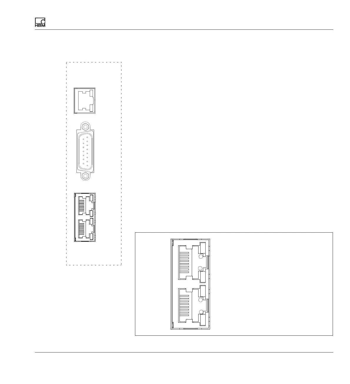
You can synchronize any number of DMP41s via the synchronization sock
ets (SYNC.IN and SYNC.OUT). The connected DMP41s are automatically
detected and synchronized when the SYNCH sockets are occupied.
The first DMP41 (Master) must be connected via the output socket
(SYNC.OUT) to the input socket (SYNC.IN) of the subsequent DMP41
(Slave). Additional DMP41s can be interconnected as required, always via
the output and input sockets.
The Master/Slave status is shown via the LEDs.
Not in use
Flashing: Operational Slave device detected
Flashing: Synchronization running
Flashing: Synchronization completed
Yellow
Green
Yellow
Green
OUT
IN
SYNC
OUT
DIGITAL
IN/OUT
1-WIRE
TEMP
SYNC
IN