Electrical connections
Transducer connection
28 A03470_07_E00_00 HBM: public DMP41
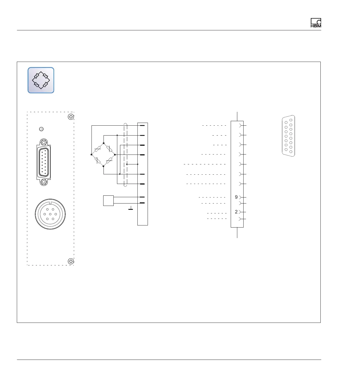
4.2.2 Full bridge strain gages
8
5
6
15
13
12
Hsg.
wh
bk
rd
bu
gn
gy
ye
1
2
4
3
Measurement signal (+)
Bridge excitation voltage (+)
Sense lead (-)
Sense lead (+)
Bridge excitation voltage (-)
Measurement signal (-)
Cable shield
1)
8
1
15
9
Cable color code: wh= white; bk= black; bu= blue; rd= red; ye= yellow; gn= green; gy= gray
Connection diagram Pin assignment
Input
Connection point
The LEDs above the connection sockets indicate the operating status of the measuring point:
LED green = Measuring point active
LED off = Measuring point passive
LED red = Error
LED orange = Transducer identification
9
2
3
Voltage supply + 16 V
Voltage supply - 16 V
ye
bk
TEDS
DATA
1-Wire® data
4
TEDS
1-Wire® ground
TEDS module (optional)
1-TEDS-BOARD