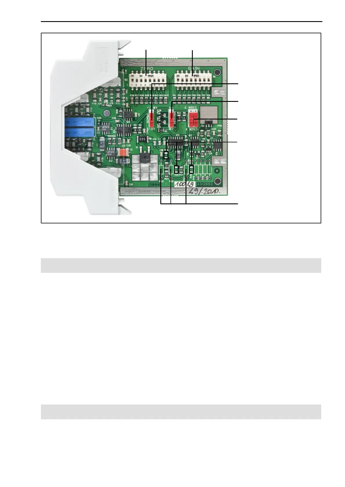
13
RM4220
A1091-4.0 en/de HBM
Output voltage (0 … 10V)
Excitation voltage (10V)
Four‐wire or six‐wire
configuration (four‐wire)
GAINZERO
Resistors for filter (SMD)
Resistors for filter
(conventional technology)
Fig. 5.2: Motherboard and position of DIP switch with opened housing, factory set
ting is shown in the image and in brackets
5.2 Setting the DIP switches
• OUTPUT sets the voltage output:
10V and 4 … 20mA
0 … 10V and 4 … 20mA (switch position as in image, factory setting)
• EXCITATION sets the excitation voltage for the transducer:
5V
DC
10V
DC
(switch position as in image, factory setting)
• 6 WIRES and 4 WIRES change the switching type (both switches must
have the same position):
Six‐wire configuration
Four‐wire configuration (switch position as in image, factory setting)
5.3 Setting up the zero point
The zero point is set with ZERO (Fig. 5.2) and the Zero potentiometer (Front).