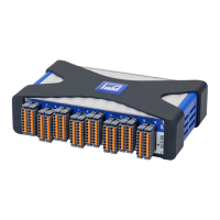
RM4220
14
A1091-4.0 en/deHBM
Null(mVV)
R
Bridge
1000
4
R
W
R
Bridge
The table shows the adjustable misalignments for R
Bridge
=350Ω and
R
Bridge
=87Ω.
ZERO R
ZERO
Zero for R
Bridge
= 350 W Zero for R
Bridge
= 87 W
Ω mV/V mV/V
1 3.9⋅10
6
0.020 (factory setting) 0.005 (factory setting)
2 2.2⋅10
6
0.035 0.009
3 750⋅10
3
0.110 0.028
4 301⋅10
3
0.280 0.070
5 121⋅10
3
0.710 0.175
6 49900
1.730 0.430
7 21000
4.000 1.000
8 9090
9.200 2.300
Set the coarse value with the ZERO DIP switches, the fine adjustment can be
implemented with the Zero potentiometer on the front.
5.4 Set amplification
The amplification is set with GAIN (Fig. 5.2) and the Gain potentiometer
(Front). To achieve the highest possible measured value resolution, you should
use the maximum output voltage of the amplifier (10V).
Partialload
Nominalload
Meas.rangeinV
10V
SensitivityinmVV Nom.meas.range(Range)inmV
The table shows the measuring ranges that can be adjusted with GAIN
dependent on the bridge excitation voltage V
E
.
GAIN V
E
= 5V V
E
= 10V
mV/V mV/V
1 11.76 - 25 (factory setting) 5.88 - 12.5 (factory setting)
2 6.06 - 12.9 3.03 - 6.45
3 2.94 - 6.25 1.47 - 3.125
4 1.54 - 3.28 0.77 - 1.64
5 0.84 - 1.74 0.42 - 0.87
6 0.46 - 0.96 0.23 - 0.48
7 0.234 - 0.5 0.117 - 0.25
8 Not used Not used


 To Next Page