Page
43
Heathkit
Install parts in
Section 4 of
the
circuit board as fol-
lows:
(
)
R368: 2000
(2
k)
ft control (#10-318).
(
)
C336: 2.2 \xF
electrolytic capacitor.
(
)
C333: 100 jxF
electrolytic capacitor.
(
)
R329: 500
kfl control
(#10-946).
(
)
C319: 10
fiF,
25
V
electrolytic capacitor.
(
)
C357:
10 \lF, 25 V
electrolytic capacitor.
(
)
C359:
220 jjlF
electrolytic capacitor.
(
)
Solder the leads to
the foil and cut off the ex-
cess lead
lengths.
Refer
to
Pictorial
2-8
(Illustration Booklet, Page
16)
for the
following steps.
( )
Prepare the following violet solid
wires. These
wires are listed
in the order in which you will
use
them.
5"
6-3/4"
3"
7/8"
1-3/4"
2"
1-7/8"
1-1/2"
3-1/2"
5-1/4"
Install the prepared wires
in the circuit board as
fol-
lows. Be sure to position each
wire as shown
in the
Pictorial.
(
)
5"
from hole A to
hole A.
(
)
3"
from hole
B to hole B.
(
)
1-3/4"
from hole L to hole L. Be
sure
to
route
this
wire under the leads
coming from R431
and D409 as
shown.
(
)
1-7/8"
from hole D to
hole D.
(
)
3-1/2"
from hole C to
hole
C.
(
)
6-3/4"
from hole E to hole E.
Be sure to route
this wire under the lead
coming from D409
as
shown.
(
)
7/8"
from
hole K
to
hole K.
(
)
2"
from hole
J
to hole
J.
Be sure to route
this
wire under the lead
coming from R348 as
shown.
(
)
1-1/2"
from hole F to
hole F.
(
)
W304:
5-1/4"
wire.
(
)
Solder the leads to
the foil and cut off the ex-
cess
lead lengths.
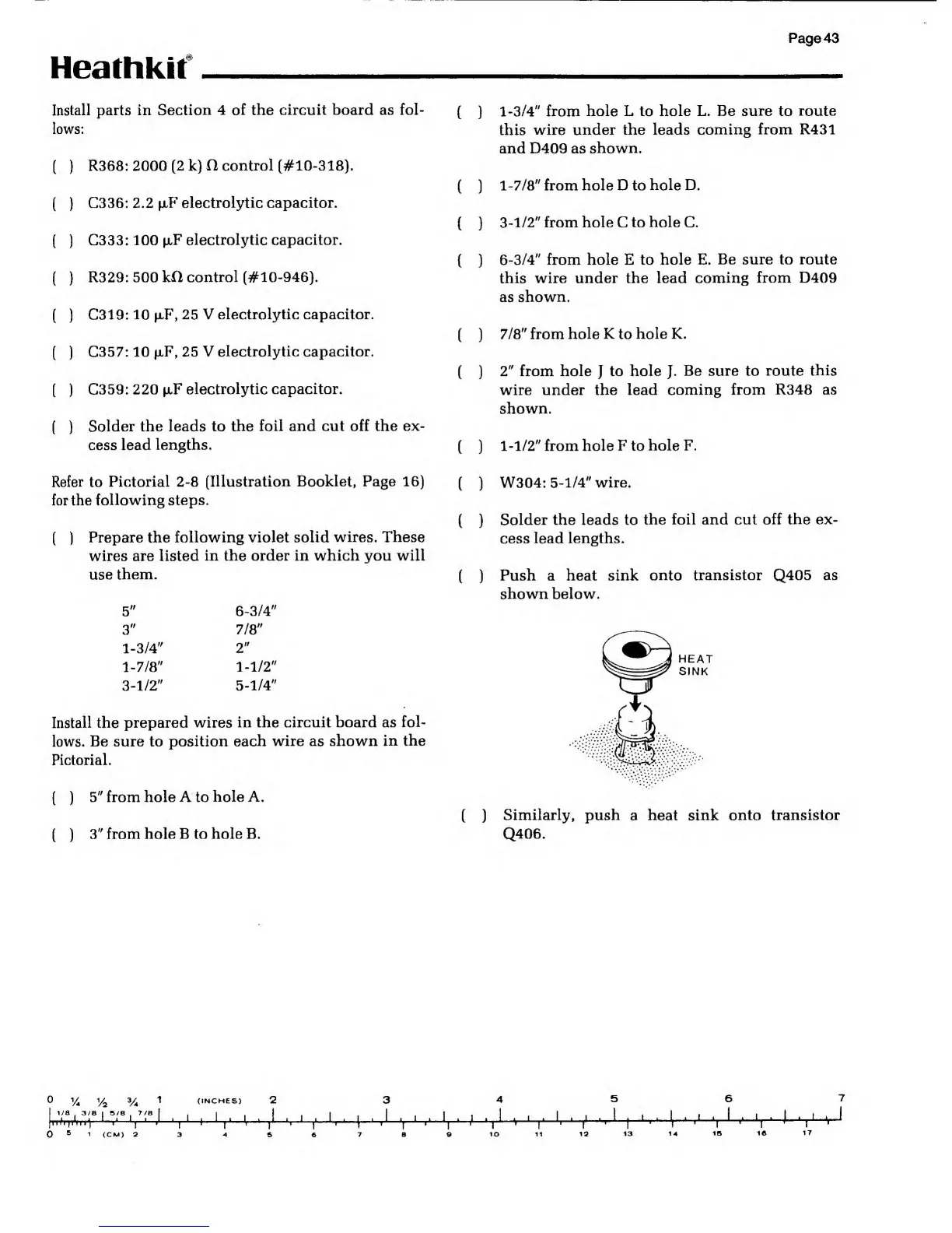
(
)
Push a heat sink
onto transistor
Q405
as
shown below.
HEAT
SINK
( )
Similarly,
push a heat sink
onto transistor
Q406.
(INCHES)
6
TT
1/8
. 3/8 I 5/8 .
7/8
*7
A
I I '|
1
(CM) 2 8
10 11
r
12
I
t
13 14
Y
15 1©
T
17
i