Page
54
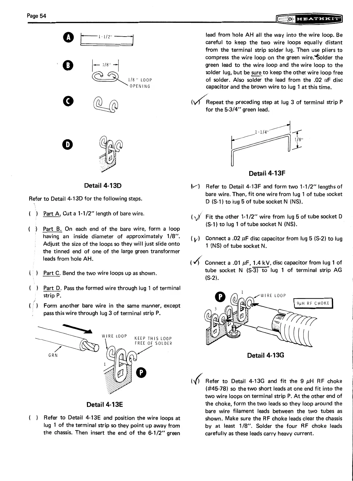
Detail 4-13D
Refer to Detail
4-13D
for the following steps.
(
)
Part A. Cut a
1-112"
length of bare wire.
(
3
Part
B.
On each end of the bare wire, form
a
loop
having an inside diameter of approximately
118".
,
Adjust the size of the loops so they will just slide onto
the tinned end of one of the large green transformer
leads from hole AH.
(
'
Part C. Bend the two wire loops up
as
shown.
(
1
Part D. Pass the formed wire through lug
1
of terminal
strip
P.
(
'
Form another bare wire in the same manner, except
I
pass this wire through lug
3
of terminal strip P.
IS
LOOP
SOLDER
Detail 4-13E
(
)
Refer to Detail
4-13E
and position the wire loops at
lug
1
of the terminal strip so they point up away from
the chassis. Then insert the end of the
6-112"
green
lead from hole AH all the way into the wire loop. Be
careful to keep the two wire loops equally distant
from the terminal strip solder lug. Then use pliers to
compress the wire loop on the green wire.%lder the
green lead to the wire loop and the wire loop to the
solder lug, but be =to keep the other wire loop free
of solder. Also solder the lead from the
.02
uF disc
capacitor and the brown wire to lug
1
at this time.
the preceding step at lug
3
of terminal strip P
for the
5-314"
green lead.
Detail 4-13F
M
Refer to Detail
4-13F
and form two
1-112"
lengths of
bare wire. Then, fit one wire from lug
1
of tube socket
D
6-11
to lug
5
of tube socket
N (NS).
(
\J'
Fit the other
1-112"
wire from lug
5
of tube socket D
(S-1)
to lug
1
of tube socket
N (NS).
(
~j)
Connect
a
.02
pF disc capacitor from lug
5 (S-2)
to lug
1
(NS)
of tube socket
N.
(
4
Connect a
.O1
pF,
-
1.4
kV, disc capacitor from lug
1
of
tube socket
N
6-31
to lug
1
of terminal strip
AG
(S-2).
Detail 4-13G
(4
Refer to Detail
4-136
and fit the
9
fiH RF choke
(#45-78)
so the two short leads
at
one end fit into the
two wire loops on terminal strip
P.
At the other end of
the choke, form the two leads so they loop around the
bare wire filament leads between the two tubes as
shown. Make sure the RF choke leads clear the chassis
by at least
118".
Solder the four RF choke leads
carefully as these leads carry heavy current.