101
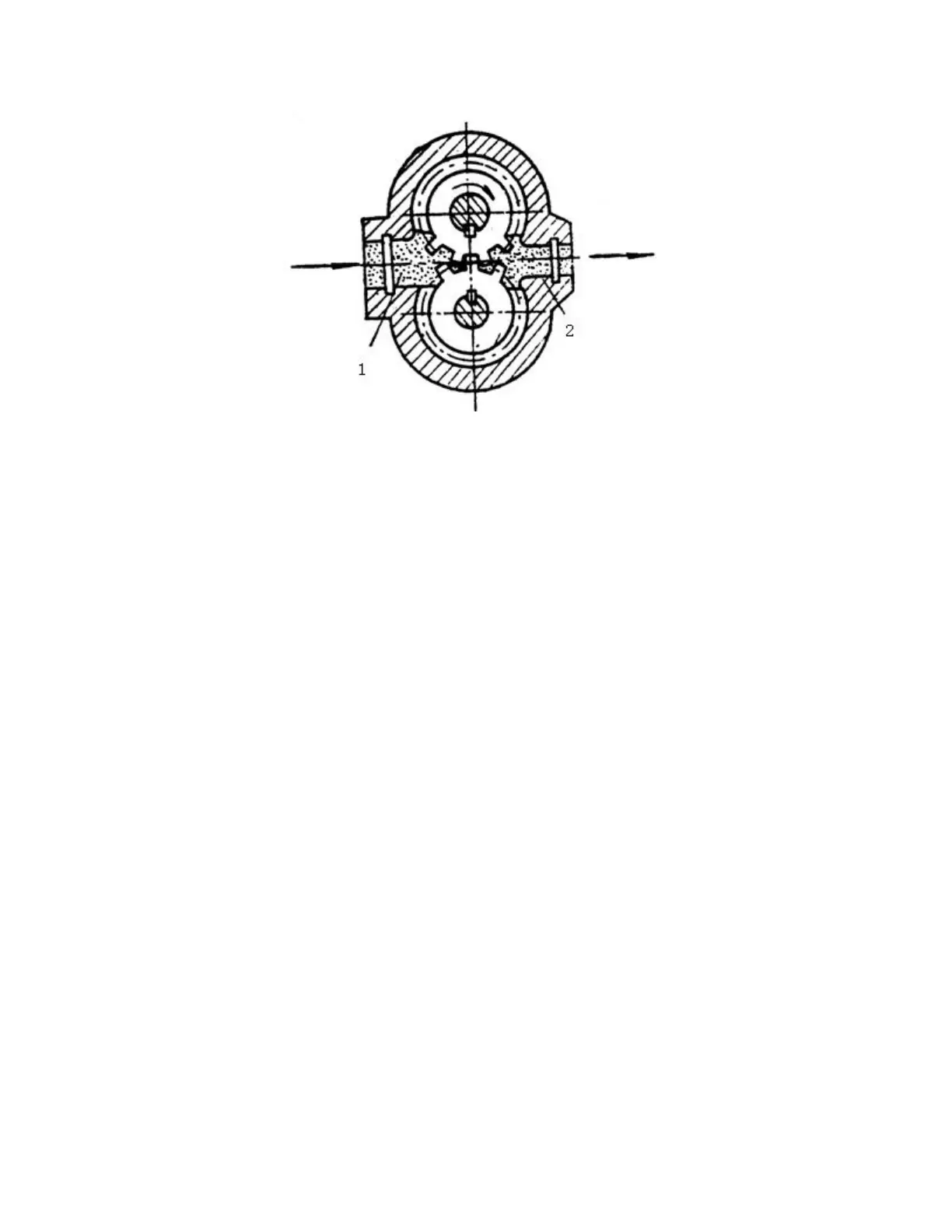
Fig 5-1 Working principle of gear pump
(1) Oil suction cavity (2) Oil pressing cavity
A pair of meshed involute gear is mounted inside the housing, the two end face seals
of gear and gear separate the pump housing into two sealing oil cavities as shown 1 and 2
in the Fig. When the gear of gear pump rotates in the direction shown in the Fig, the
volume of space shown by 1 (engaging part for gear disengagement) changes from small
to big and forms vacuum. The oil in the oil tank enters into oil suction cavity under the
action of atmospheric pressure to fill the intertooth space through the oil suction pipe of
pump. While 2 indicates that the volume of space (engaging part for gear entering)
changes from big to small and press the oil into pressure oil circuit, i.e.1 is oil suction
cavity, 2 is oil pressing cavity and they are separated by meshing point of two gears. With
constant rotation of gear, the suction and discharge outlets of the pump continuously
absorb and drain oil.
Oil pump is to turn the mechanical energy of motor into hydraulic energy, so the oil
pump is the actuating unit of hydraulic system of the forklift.
The main pump consists mainly of a pump body, a pair of gears, lining plates and oil
seals. This pump uses pressure-balance type bearings and a special lubrication method so
as to minimum the clearance of the gear face. (See Fig. 5-2)
 Loading...