30
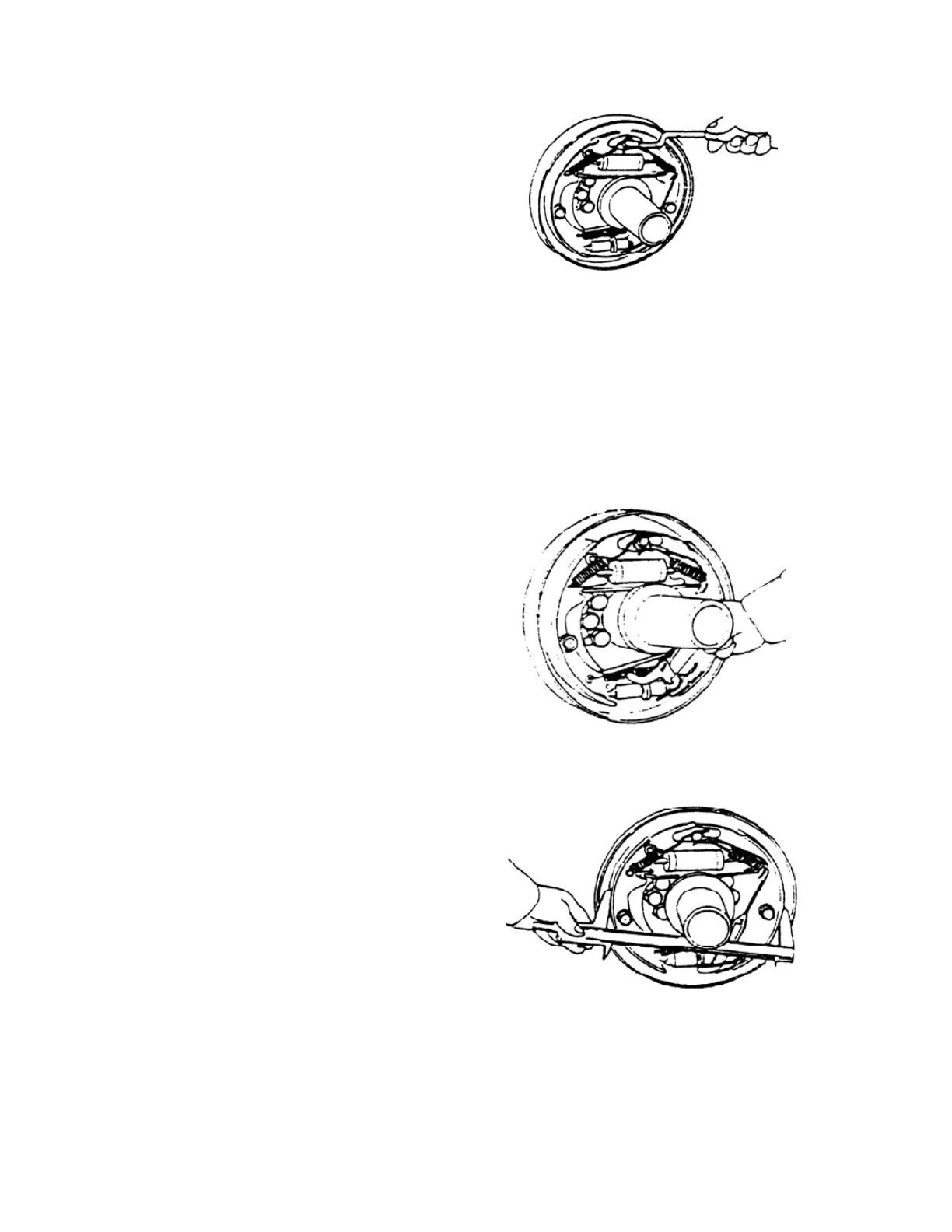
(8) Install the shoe guide plate on the
anchor pin, and install the shoe return
spring. Install the main shoe first and then
secondary shoe. (See Fig. 2-22)
Fig. 2-22
(9) Install the adjuster, adjuster spring, push rod and its return spring.
Pay attention to the following points:
a) Adjuster thread direction and its mounting direction.
b) Adjuster spring direction. (Do not allow the adjuster gear teeth to contact with the
spring)
c) Return spring direction of the push
rod: Spring hook at anchor pin side should
be located at the opposite side to push rod.
d) Make sure that the adjusting lever
end is in contact with the adjuster gear
teeth. (See Fig. 2-23)
Fig. 2-23
(10) Install the brake line on the operating cylinder.
(11) Measure the inner diameter of
drum and the outer diameter of brake shoe.
Adjust the adjuster to obtain the 1mm
difference needed between the drum inner
diameter and the friction piece outer
diameter. (See Fig. 2-24)
Fig. 2-24
2.2.4 Operation test to clearance-self-adjuster
(1) Make the brake shoe diameter approach the specified mounting size, and pull the