108
The pressure of the safety valve shall not be adjusted by non-professional personnel.
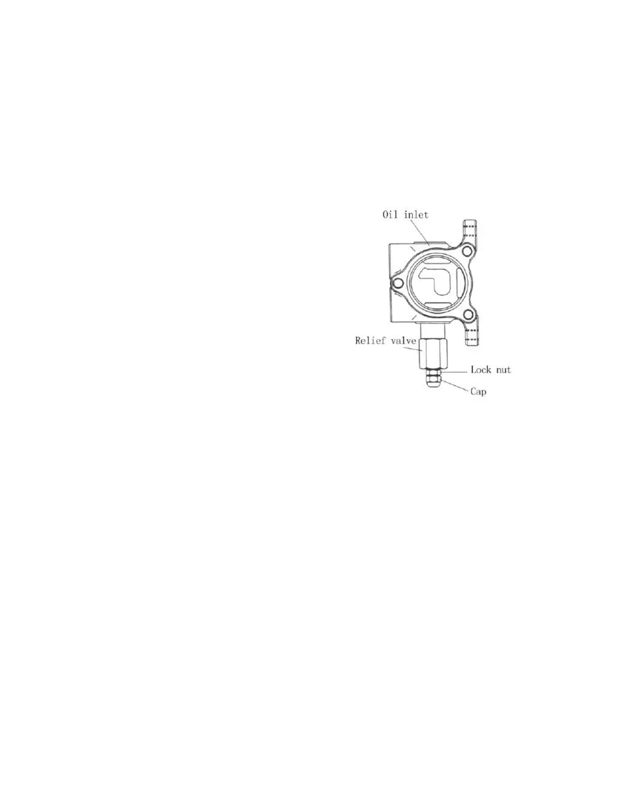
The adjustment shall follow following procedures:
a) Screw off the plug of the measuring hole on the inlet of the control valve. Install
an oil pressure gauge capable of measuring 25MPa.
b) Operate tilting lever and measure the pressure at the end of the cylinder stroke.
c) If the oil pressure is different
with the specified value, loosen the
locking nut of the relief valve and turn
the adjusting screw left and right until
the pressure reaching the specified value.
Turn left when the pressure is high and
turn right when the pressure is low.
d) Tighten the nut after adjusting.
Fig. 5-15
5.1.3 Lift cylinder
The lift cylinder is of single-acting piston type. It consists of cylinder body, piston,
piston rod, cylinder cap, cut-off valve and oil seals. The cylinder head is equipped with
bushing and oil seal and the bushing supports the piston rod and the oil seal keeps dust
off. (See Fig. 5-16)
When the hoist valve of control valve is placed at lifting position, hydraulic oil
enters into the lower part of piston of hydraulic cylinder from pressure-gradient control
valve to selector valve to push rising of piston and lifting of the goods. When the hoist
valve of control valve is placed at descending position, the piston rod drops with the
action of goods, mast, fork bracket and piston itself, the hydraulic oil is pressed back to
oil tank. If the cut-off valve is mounted at the bottom of cylinder (See Fig. 5-17), it can
play the role of protection if the mast rises when high-pressure pipe cracks.
 Loading...