111
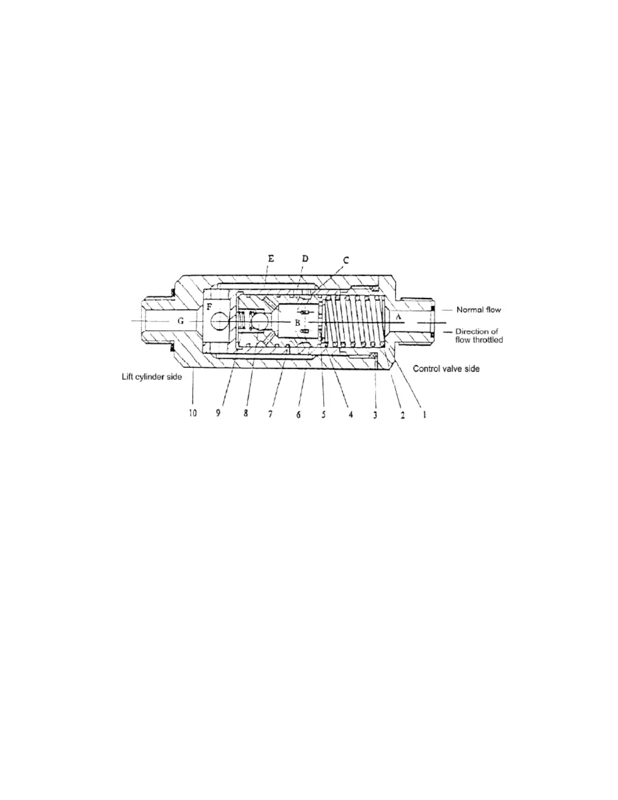
When the lift spool is placed in the “lift” position, the oil from the control valve
flows through the oil chambers A and B, oil holes C, D, E and F, and the chamber G to
the lift cylinder without any regulation. When the lift spool is placed in the “down”
position, the oil pusses the orifice plate and a pressure difference generates between the
chambers A and B, the pressure difference overcomes the force of the spring and moves
the valve core right, thus the oil flow being decreased by narrowing of the hole D and C,
and reduces the oil flow passing through the orifice plate.
Fig. 5-18 Flow regulator valve
(1) Nipple (2) Spring (3) Ring seal (4) Snap ring (5) Spool
(6) Sleeve (7) Steel ball(8) Spring of the check valve (9) Valve body
5.1.6 Tilt cylinder
The tilt cylinder is of double-action and piston type hydraulic cylinder and is
mounted at both sides of mast with its piston rod end connecting with mast. The bottom
of tilt cylinder is connected through dowel with connecting end of frame and mast and the
forward and backward tilting of the mast are fulfilled by the motion of tilt cylinder.
The tilt cylinder consists primarily of piston, piston rod, cylinder body, cylinder base,
guide sleeve and seals. The piston, welded to the piston rod, is fitted with two Yx-rings
and one wear ring on its circumference. A bushing press-fitted to the inner side of the
guide sleeve supports the piston rod. The guide sleeve is with dust seal, snap ring,
 Loading...