118
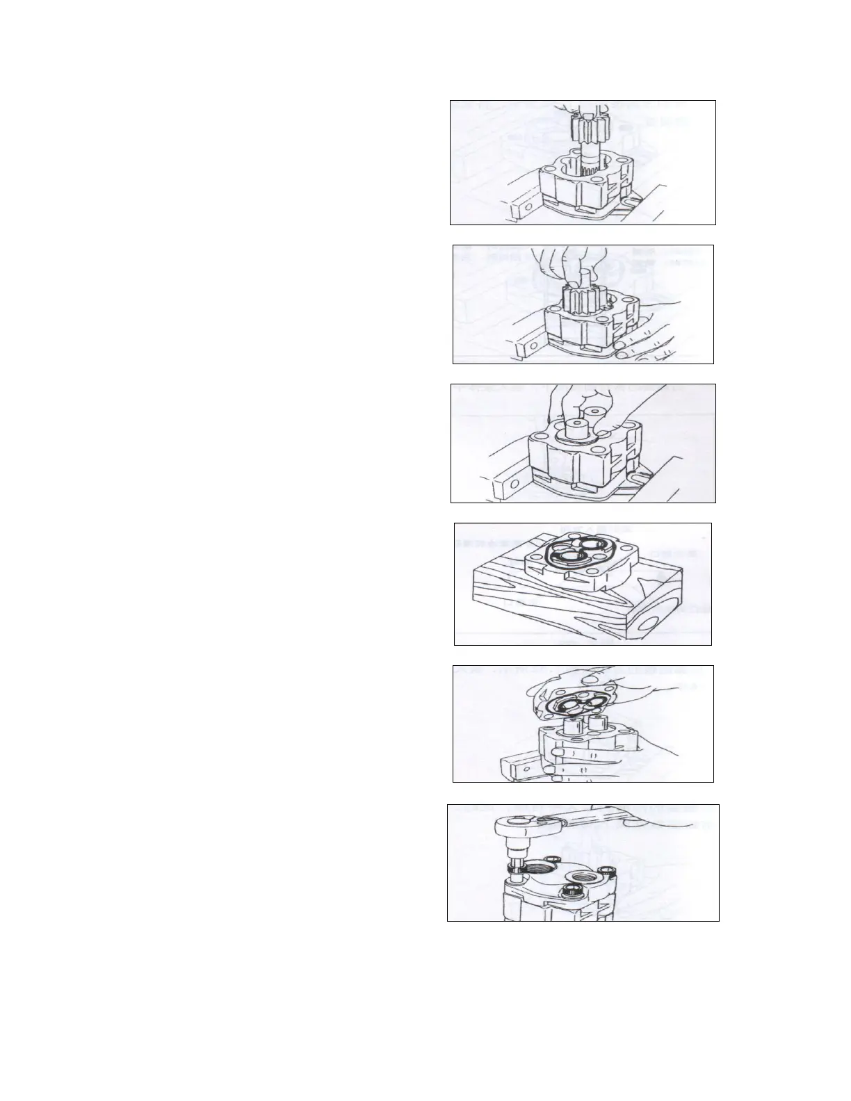
f) Install the drive gearon the pump
body with the side of the spline
downward.
Fig. 5-33
g) Install the driven gear on the pump
body as the direction shown in Fig. 5-34.
Fig. 5-34
h) Install the lining plate on the
side of the gear, don’t confuse the inlet oil
port and the outlet oil port.
Fig. 5-35
i) Install a new seal ring and a new
ring on the groove of the rear cover. Apply
lubricating grease on the seal ring.
Fig. 5-36
j) Install the rear cover on the pump
body with it’s seal ring downward, don’t
confuse the inlet oil port and the outlet oil
port.
Fig. 5-37
k) Tighten up the connecting bolts
with a specified torque of 9 to 10kg.m
after all.
Fig. 5-38
 Loading...