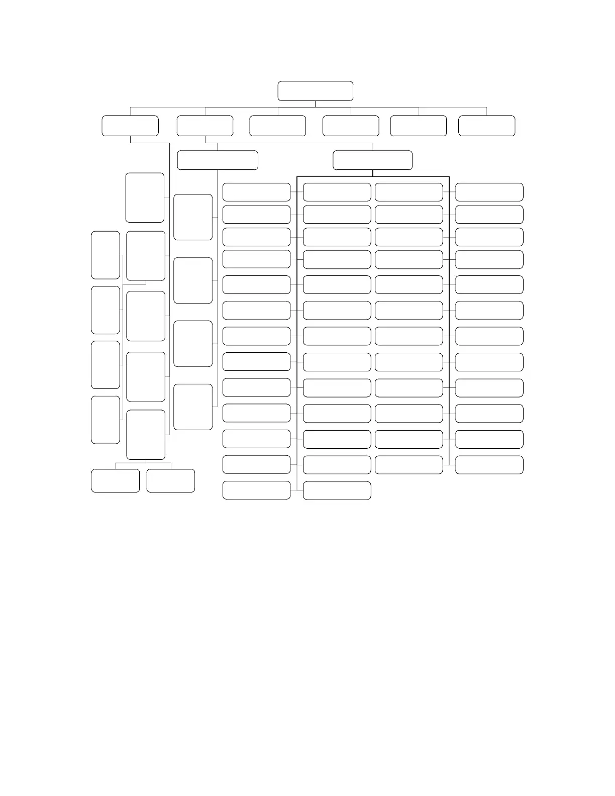
Main display interface
1.Parameter setup
2.Monitoring
menu
3.Start Screen
ON/OFF
4.Type of drive
fault 1/2
5.Type of pump
control failure 1/2
6.Clock setup
1.1
Hourmeter
reset to
zero OK
Long press the enter key 5S to enter the
menu from the main display interface
1.2 Battery
parameter
setting
1.3 Liquid
crystal
contrast
percentage
1.4
Percentage
of pump
power
forbidden
1.5
Password
Setting
1.2.1
Single
charge
full
voltage
1.2.2
Single
charge
null
voltage
1.2.3
Single
discharg
e full
voltage
1.2.4
Single
discharg
e null
voltage
1.5.1 The
password input
1.5.2 New
password
2.1 Drive motor
controller monitoring
2.2 Pump motor
controller monitoring
2.2.1 Pump
motor
phase
current
2.2.2 Pump
motor
speed
2.2.3 Pump
controller
temperature
2.2.4 Pump
motor
temperature
2.1.1 Accelerator
instruction
2.1.2 Accelerator
mapping
2.1.5 brake pedal
mapping
2.1.6 brake pedal
voltage
2.1.9 Interlock
condition
2.1.3 accelerator
voltage
2.1.4 brake pedal
instruction
2.1.7 simulator 1
input
2.1.8 simulator 2
input
2.1.10 specified
direction
2.1.11 switch 1 status
2.1.13 switch 3 status
2.1.14 switch 4 status 2.1.15 switch 5 status 2.1.16 switch 6 status
2.1.17 switch 7 status 2.1.18 switch 8 status
2.1.12 switch 2 status
2.1.19 switch 16
status
2.1.20 driver 1 status
2.1.21 driver 2 status 2.1.22 driver 3 status 2.1.23 driver 4 status 2.1.24 driver 5 status
2.1.26 driver 7 status2.1.25 driver 6 status
2.1.27 inside 15V
output
2.1.28 5V output
2.1.29 12V output
2.1.33 Proportional
drive output
2.1.37 Lock line
voltage
2.1.41 Controller
temperature
2.1.45 Controller
overtemperature limit
2.1.49 Regeneration
limit
2.1.30 External
supply current
2.1.34 driver 3 output
2.1.38 motor speed
2.1.42 Main
contactor status
2.1.46 Under voltage
limit
2.1.50 battery voltage
2.1.31 Main
contactor driver
2.1.35 output torque
2.1.39 motor
temperature
2.1.43 running status
2.1.47 Overvoltage
limit
2.1.32 Proportional
control current
2.1.36 capacitor
voltage
2.1.40 Speed phase
current
2.1.44 Motor
overtemperature limit
2.1.48 Drive fault
limit ratio
(2)Parameter description corresponding to the numbered part of the above table
◆Start screen ON/OFF: Enable and turn off the starting screen of the instrument;
◆type of driver fault 1/2:1 represents that the communication type of driver fault is
CAN communication, 2 represents that the communication type of driver fault is Fault
code communication; (instrument with this function can be configured with this)
◆Type of pump control failure 1/2: 1 represents that the communication type of
pump control failure is CAN communication, 2 represents that the communication type of
pump control failure is Fault code communication; (instrument with this function can be