23/34
8 Assembling and disassembling components
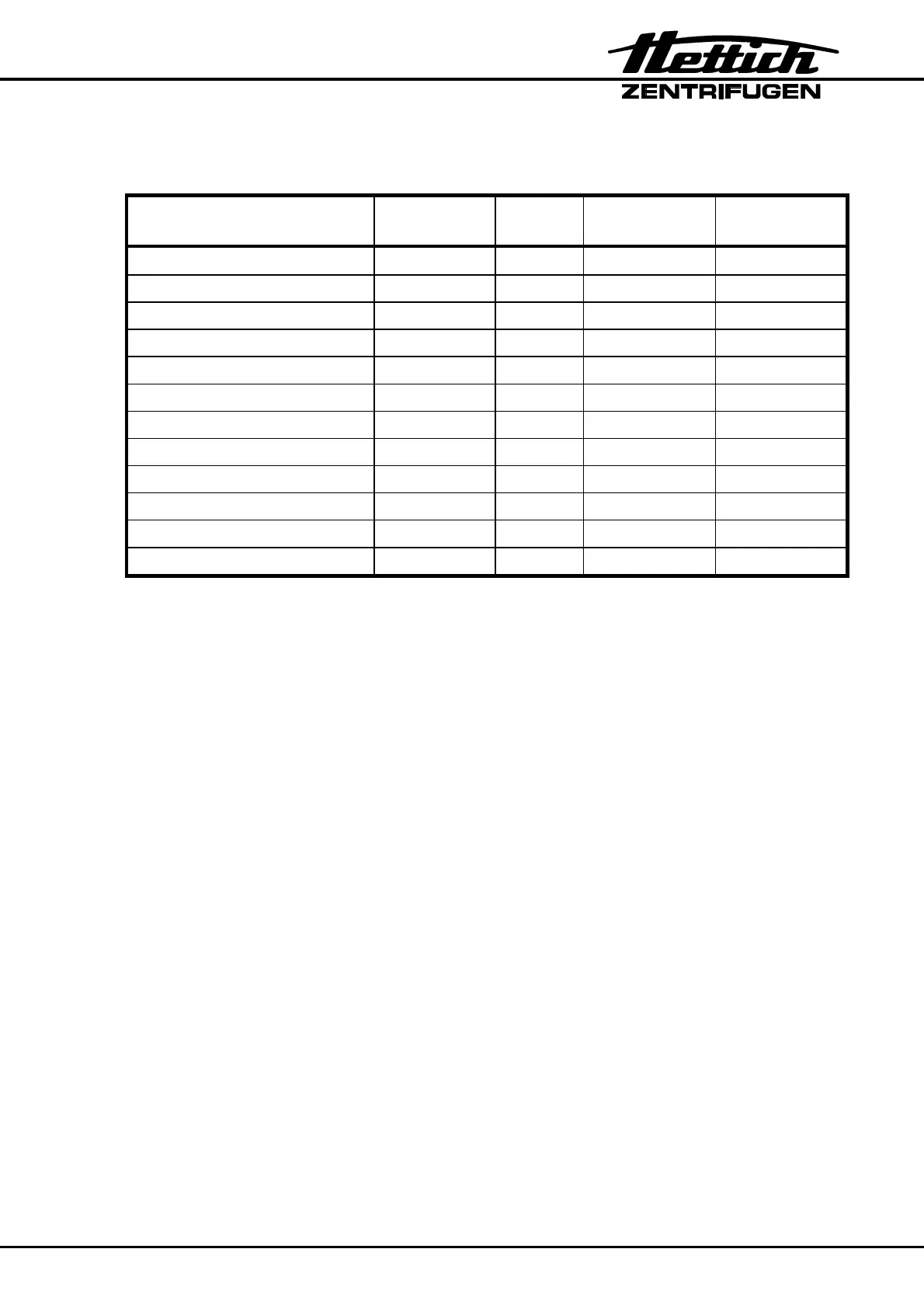
Component Abbreviation Plug Connected to Description in
chapter
Speed sensor B3 S502 A1 8.1
Motor M1 S401 A1 8.2
Rubber-metal bearing -- -- 8.2
Power board A1 -- -- 8.3
Control panel A3 -- -- 8.4
Flat ribbon cable A1 to A3 8.7
Lid lock Y1 S404 A1 8.11
Brake resistor R1 S405 A1 8.5
Overtemperature fuse F3 S405 A1 8.6
Mains switch Q1 -- A1 8.8
Appliance plug -- -- -- 8.8
Imbalance switch S1 S503 A1 8.10
Before assembling or disassembling components, the following working processes must
first be carried out to reach the components.
Make a note of the plug numbers !
The components are assembled in reverse order !
• Open the lid
• Switch off the mains switch
• Disconnect the centrifuge from the mains
• Remove the rotor
• Remove the motor hood in the centrifuge chamber
• Remove the centrifuge chamber.