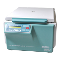
Do you have a question about the Hettich UNIVERSAL 32 R and is the answer not in the manual?
Describes the control panel as the central unit managing centrifuge operations and inputs.
Explains the functions of the power supply board, including voltage distribution and signaling.
Details the frequency converter's role in motor power supply, control, and fault monitoring.
Methodical approach to identifying and resolving detected centrifuge faults.
A summary table of error designations, numbers, brief descriptions, and page references.
Specific troubleshooting steps for TACHO-ERROR 01 and TACHO-ERROR 02.
Explains the imbalance error cause, consequences, and recommended remedies.
Details the error related to the lid being unexpectedly open during centrifugation.
Describes the error for exceeding maximum speed and its troubleshooting.
Addresses errors caused by invalid or unreadable rotor codes detected at startup.
Explains errors resulting from interruptions in the mains power supply during operation.
Details errors related to insufficient motor speed or excessive slippage.
Explains various internal errors detected within the control panel (CP) unit.
Addresses errors for exceeding the maximum permissible rotor speed or RCF.
Troubleshooting for serial communication failures between the Control Panel and Frequency Converter.
Addresses issues with the Control Panel not receiving correct data from the Frequency Converter.
Step-by-step guide for initialising the centrifuge, especially after FC replacement.
Process for aligning the temperature sensor and control panel electronics for accurate readings.
Additional checks required to ensure the centrifuge operates correctly after repairs.
Detailed schematic of the supply board, showing components and internal connections.
Visual guide to component placement and external wiring on the supply board.
Explanation of signals transmitted via the control cable between the Control Panel and Supply Board.
Block diagram illustrating the internal structure, inputs, and outputs of the control board.
Block diagram of the FC and its control cable signals, showing interaction with the Supply Board.
Schematic showing the Frequency Converter's connections to the motor and other components.
| Temperature Range | -20°C to +40°C |
|---|---|
| Capacity | 4 x 100 ml |
| Control Panel | Digital |
| Power Supply | 230V, 50/60 Hz |
| Type | Centrifuge |
| Max Speed | 15000 rpm |
| Timer | 1 sec to 99 hours 59 min |
| Motor | Brushless |


 Loading...