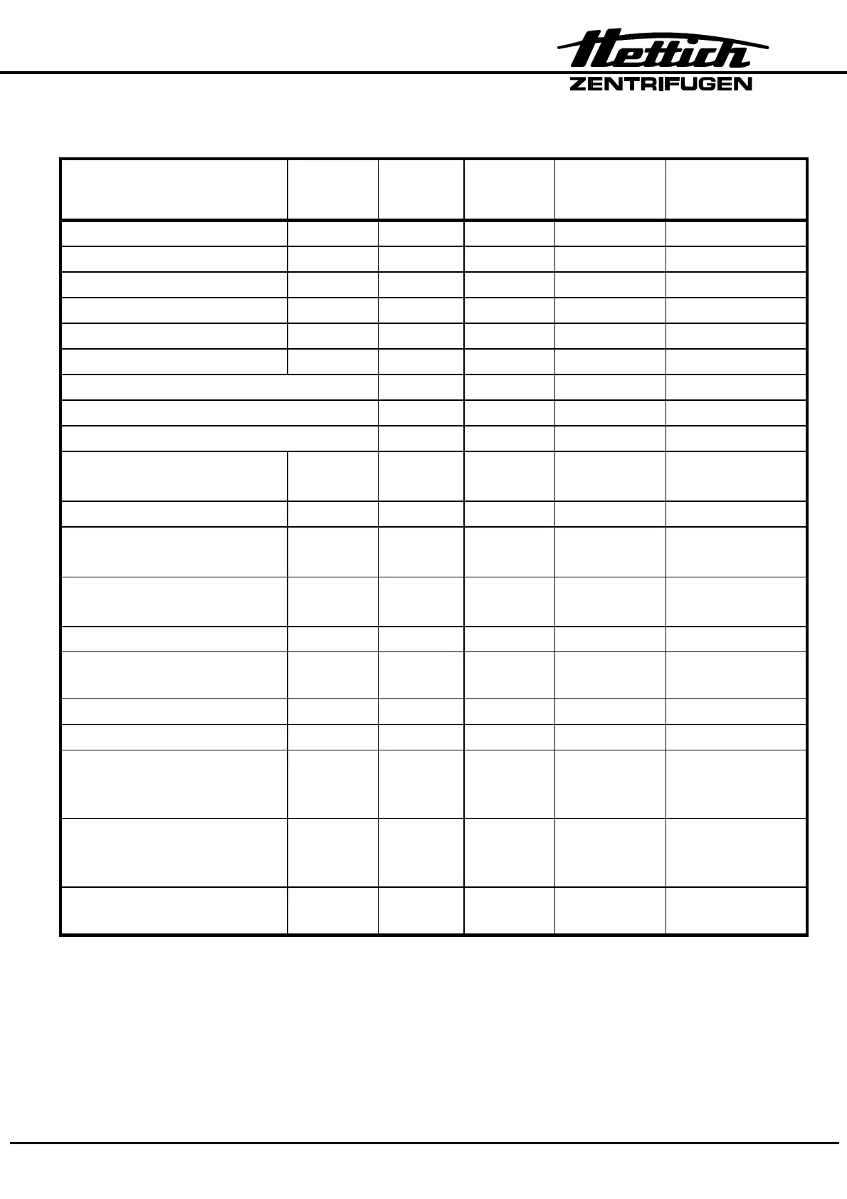
33/49
11. General arrangement of the component
Components Abbreviatio
n
Plug
connection
Connection
at boards
Circuit
diagram in
section
Described in
section
Tacho sensor B3 X4 A1 13.1, 13.3 12.4
Motor / rubber metal bearing M1 S101 A2 13.7, 13.8 12.5
Frequency converter A2 A2 13.7, 13.8 12.6
Supply board A1 A1 13.1, 13.3 12.9
Control board A4 A3 13.5, 13.6 12.2
EPROM (on CP) A3 12.3
Control cables 10-conductor A1-A2 13.1, 13.7 ---
16-conductor A1-A4 13.1, 13.6 ---
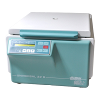
only UNIVERSAL 32 R 10-conductor A3-A4 13.6, 13.10 ---
Lid lock Y1 X5-S1
(X9-S1)
A1 13.1, 13.3 12.15
Brake resistor R1 P10, P1 A2 13.7, 13.8 12.7
Overtemperature fuse F3 Y1-X5
(X9-Y1)
13.7, 13.8 12.8
Radio inference suppression
filter
Z1 X9-S1
(X10-S1)
A1 13.1, 13.3 12.10
Mains choke coil L1 - - 13.8 12.11
Mains switch „ON-OFF“ S1 Z1-X5/Y1
Z1-
13.1 12.12
Appliance plug X9 Z1 13.1 12.13
Imbalance switch S1 X3 A1 13.1, 13.3 12.14
Temperature sensor
chamber
(only UNIVERSAL 32 R)
B1 X6 A1 13.1, 13.3 12.17
Temperature sensor
condenser
(only UNIVERSAL 32 R)
B2 X7 A1 13.1, 13.3 12.18
Cooling board
onl
UNIVERSAL 32 R
A3 A1 13.9, 13.10 12.16