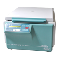
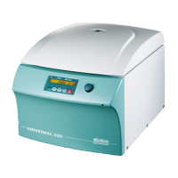
CP : control panel, FC : frequency converter, SB : supply board, CB : cooling board, CC : control cable, LL : lid locking, BC : braking chopper,
BR : brake resistor, MR : mains reset
6/49
2.3. Supply board (SB)
The SB performs the following individual functions:
• 12 V DC and 5 V DC supply for the SB.
• 12 V DC supply for the CP.
• 12 V DC supply for the CB (only UNIVERSAL 32 R).
• Plugging station X5 for mains power supply, LL magnet and transmission of the
signalling circuit for LL-switch (open/closed over opto-coupler to the CP).
• Power supply for speed sensor (speedometer).
• Plugging station X4 for speed sensor cable an0d transmission to the CP and FC.
• Control of the relay for the LL solenoid at rotor standstill
• Plugging station X3 for the imbalance switch and direct transmission of the
imbalance signal to the CP.
• The 5 Volt interface with 3 conductors is converted to an RS 485 interface with 2
conductors:
• Interface to FC: RS 485-interface via 2 conductors.
• Transfer of primary enabling (=Hardware STOP) CP ⇒ FC
• Transfer of fault circuit (FC-ERROR) FC ⇒ CP
2.4. Frequency converter (FC)
The FC performs the following individual functions:
• Generation of the motor power supply.
(3-phase AC current of variable frequency and voltage)
Mode of operation: The mains supply is rectified, smoothed and chopped in three
bridge elements to give a pulse-duration modulated supply.
• Monitoring of the motor current.
• Evaluation of the overtemperature switch in the motor (only version 115V, AC).
• Slave behaviour (handling of interrogations and commands from the CP via the
serial interface):
RS 485-interface with 2 conductors
(10-pole control cable, pole 3 and 5).
• Evaluation of the primary enabling (Hardware STOP) for the FC
(10-pole control cable, pole 7).
• Evaluation of potential faults and monitoring of the fault circuit (FC-ERROR)
(10-pole control cable, pole 4).
• The electrical power, which resulted from braking, will be conducted to the BR. The
braking chopper switches at a voltage:
− from approximately 390V (230V series).
− from approximately 200V (115V series).
• The BR is protected by an overtemperature fuse. At a short circuit on the BC, which
is located on the FC, the BR overheats because of high current. The
overtemperature fuse cuts off the voltage supply from the FC.
 Loading...
