Installation
14
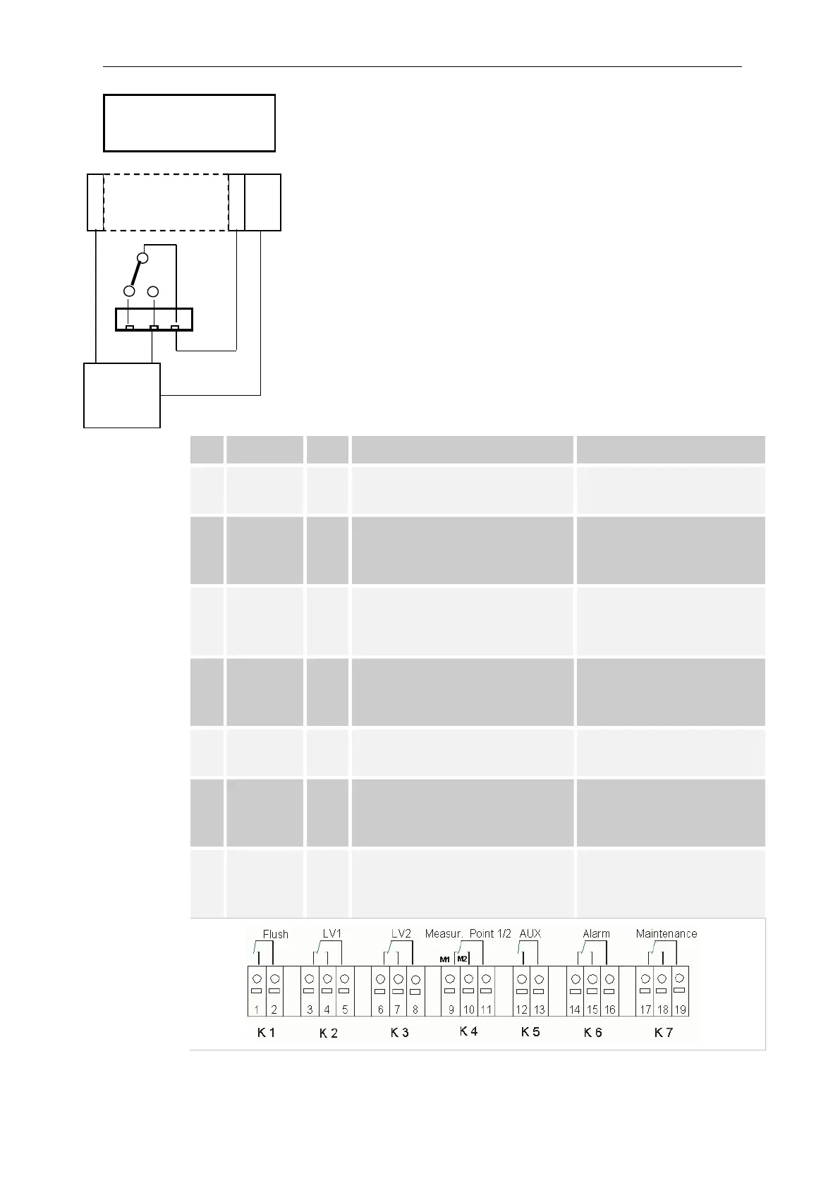
Connecting the plant components
Connect the plant components to the output terminals of relays 1
to 19 (e.g. valves).
If the plant components require mains voltage, connect the
switched mains voltage (l) to the common contact of the
respective relay (see the connection example for 230 VAC on the
left).
Connect the neutral conductor of the plant component to one of the
terminals (n).
For components with a protective earth conductor connection,
connect it to the PE connection.
Ensure that the leads are held securely in the terminals.
(Drawn relay positions: Instrument de-energised)
No.
Terminal
Type
Function Comment
1
2
Flush OUT
External flush valve
Isolated relay output, max.
240 VAC, 4 A
3
4
5
LV1 OUT
Limit value output 1 – N/C
Limit value output 1 – N/O
Limit value output 1 - Common
Isolated relay output, max,
max. 240 VAC, 4 A
6
7
8
LV2 OUT
Limit value output 2 – N/C
Limit value output 2 – N/O
Limit value output 2 - Common
Isolated relay output, max.
240 VAC, 4 A
9
10
11
M. point.
1/2
OUT
Measuring point 1 – N/C
Measuring point 2 – N/O
M. point switch-over - Common
Isolated relay output, max.
240 VAC, 4 A
12
13
AUX OUT
Universal output
Isolated relay output, max.
240 VAC, 4 A
14
15
16
Alarm OUT
Fault message output – N/C
Fault message output – N/O
Fault message output - Common
Isolated relay output, max.
240 VAC, 4 A
17
18
19
Maintenan
ce
OUT
Maintenance message – N/C
Maintenance message – N/O
Maintenance message - Common
Isolated relay output, max.
240 VAC, 4 A
Connection example
Limit value contact LV 1
switches mains voltage
n
l
e.g.
solenoid
valve
PE