July 2016 Page 9 of 25
see
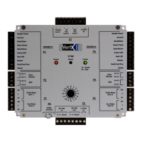
VertX EVO V1000 User Guide, 71000-901, Rev. A.4
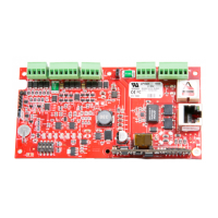
3. RS-485 Connections: The V1000 has two RS-485 connectors and uses the 10-pin
connector on P3 and P4. Each RS-485 bus can support a maximum of 16 V100-Series
panels using one or two ports.
Having two ports on each bus provides the option of splitting each RS-485 bus into
two physical connections, allowing a total of four physical connections for the two
busses.
RS-485 busses must be connected in a daisy chain topology and not a star topology.
The V1000 RS-485 termination jumper should be in the Out position if there are no
panels attached to the port. If there are downstream panels attached then the
termination jumper should be in the In position.
2 B 9 B
4 Not in use 7 Not in use
6 A 5 A
8 Shield 3 Shield
9 Not in use 2 Not in use
10 Not in use 1 Not in use
CAUTION: The V1000 RS-485 Ports 1 & 2 (P3) are a common bus and therefore
cannot have panels with duplicate Interface Addresses assigned. The same is true
of the V1000 RS-485, Ports 3 & 4 (P4). For example, two panels, both with
Interface Address 0 (factory default), cannot be connected to Ports 1 and/or 2 (P3).
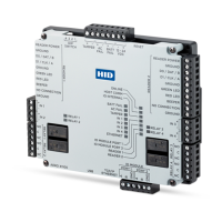
Wire the RS-485 to the In position only of the P9 terminal block for the V100-Series
panel. This is especially important when the RS-485 communication is in a “daisy
chain” configuration. If the RS-485 is wired In and Out, and power is lost, or the P9
terminal block is unplugged on a V100-Series panel, RS-485 communications will be
lost to downstream V100-Series panels.
 Loading...