Page 8 of 22 July 2016
VertX EVO V2000 Installation Guide, 72000-901, Rev. A.5
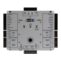
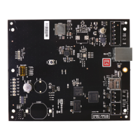
Reader Connections: Connect Wiegand or clock-and-data interfaces to a V2000 3.
using the connection table shown. You can connect up to 10 signal lines for the
reader. Use as many of the signal lines as required for your reader interface.
Note: Connect the data return line to the same ground as the reader power if the
reader is not powered by the VertX units.
Pin # V2000 P1 V2000 P4
1 Reader Power Shield Ground
2 Ground Hold
3 Data 0 / Data Beeper
4 Data 1 / Clock Red LED
5 Data Return Green LED
6 Green LED Data Return
7 Red LED Data 1 / Clock
8 Beeper Data 0 / Data
9 Hold Ground
10 Shield Ground Reader Power
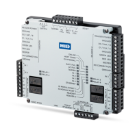
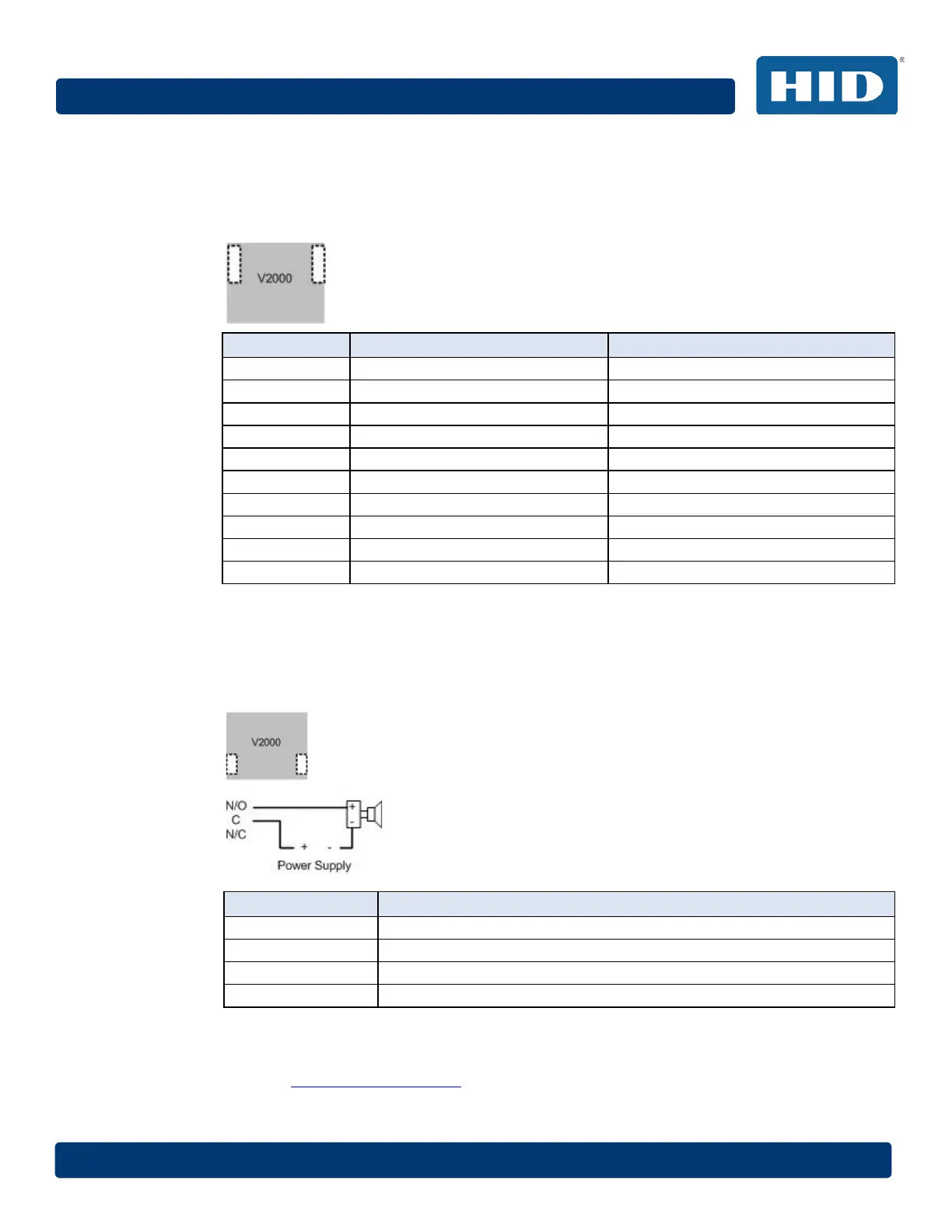
Output Connections (VertX EVO V2000): All Output connections are used for 4.
general purpose controls. The following table shows where the various outputs are
located. Pin numbers shown use the convention “NO/C/NC”. For example, Output 1,
V2000: P3 Pin 1 is NO (Normally Open,) Pin 2 is C (Common,) and
Pin 3 is NC (Normally Closed).
Note: Relays are dry contact rated for 2Amps @ 30VDC, resistive.
Output Number V2000
1 P3 Pins 1/2/3 - Strike(lock) Relay 1
2 P3 Pins 4/5/6 - Aux Relay 1
3 P6 Pins 6/5/4 - Strike (lock) Relay 2
4 P6 Pins 3/2/1 - Aux Relay 2
CAUTION: Some magnetic locks exhibit both high in-rush current when activated and a
high instantaneous break voltage when de-energized due to magnetic field collapse. Use a
snubber circuit across the controlling relay terminals to protect the controlling relay
contacts. Go to support.hidglobal.com
, see Solution 891 - How do I wire a High In-Rush
Current locking device to VertX/Edge/Edge Solo?