VertX EVO V2000 Installation Guide, 72000-901, Rev. A.5
July 2016 Page 9 of 22
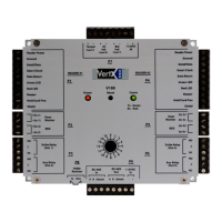
Input Connections: Input connections are analog inputs used for a combination of specific
functions such as Request-to-Exit (REX), Door monitor, etc. They can also be used as general
purpose monitoring. Connect one side of the switch or contact to the + (plus) lead and the
other to the – (minus) lead. The following table shows where the inputs are located.
Pin numbers shown on the cover use the convention +/–.
The default REX input configuration is Normally Open (NO) unsupervised (no EOL resistors).
Note: The default door switch (DS) configuration is Normally Closed (NC), unsupervised (no
EOL resistors). For UL1076 installations, all inputs must be supervised.
All other input points are defaulted for NO switches and are unsupervised (no EOL resistors).
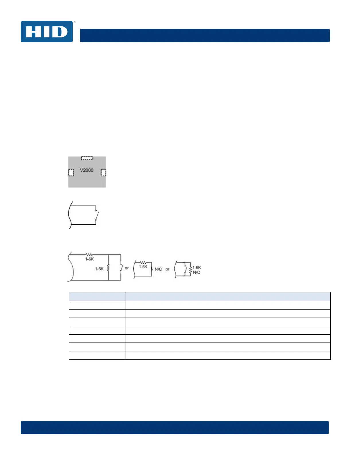
Any input can be configured as NO or NC, as well as unsupervised or supervised. They can
be configured for supervisory resistors of 1K – 6K Ohm. The setup of supervised inputs
should be done during configuration of the VertX EVO devices through the host.
Example: Input 1, V2000 is: P2 Pin 1 is + (plus) and Pin 2 is – (minus):
Except for the door monitor, all other inputs default to NO, unsupervised:
Supervised inputs can be configured for:
Input Number V2000
1 P2 Pins 1/2 - Door Monitor
2 P2 Pins 3/4 - REX input
3 P5 Pins 4/3 - Door Monitor
4 P5 Pins 2/1 - Rex Input
5 P7 Pins 8/7 - Tamper
6 P7 Pins 6/5 - AC Fail
7 P7 Pins 4/3 - Batt Fail