IM-560en
Vers. 05
Page 24
ASSEMBLY INSTRUCTIONS
VERTICAL LIFTING PLATFORM PH-300
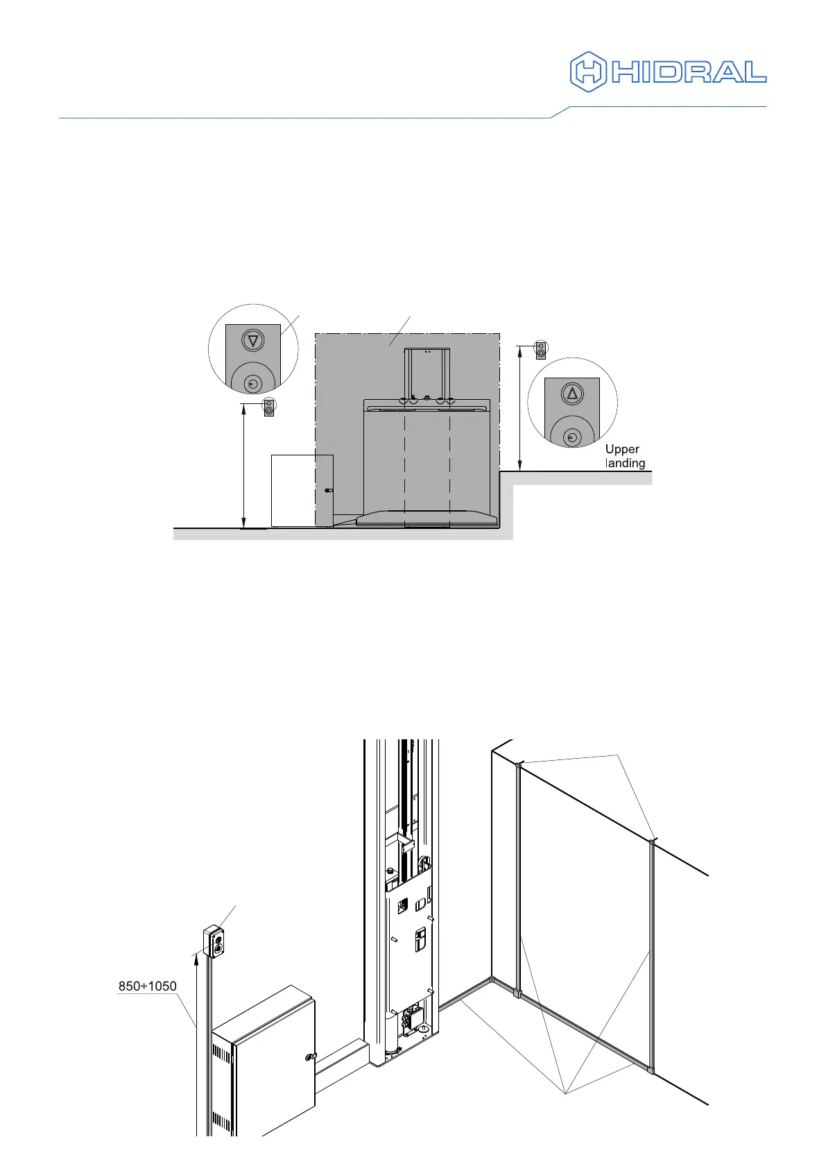
8. Landing push button panels
A push button panel is supplied for each landing level. In case an upper landing level
door is supplied, the upper push button panel is integrated in the door. Pay attention to
the direction of the arrows in the call buttons so that the upper and lower push button
panels can be differentiated. The push button panels shall be installed in a position out
of the area occupied by the vehicle when it is at the landing and so that they are easy to
access for the users. The height of the command elements should be according to what
is shown in the drawing.
Lower
landing
Parking area
Button panel
850÷1050
850÷1050
1 In case of surface mounted landing push button panels x the supplied conduits
to the wall. Install also the conduits for the upper landing level door if supplied.
In order to do so, use the template to mark the position of the conduits, which
should match the position of the slots for the cables (see "9. Upper landing door
assembly"). It is recommended that the oor is removed to x the lower conduits,
or else that the vehicle is supported so allow safe working under the oor.
2 Attach the push button panel next to the conduit, according to alternative Ⓐ with a
cabinet on the lower landing or Ⓑ with a cabinet on the upper landing.
Ⓐ Cabinet on lower landing
Slots for cables
Conduits
for door
Lower landing
push button panel
 Loading...