ASSEMBLY INSTRUCTIONS
PH-300 VERTICAL LIFTING PLATFORM
IM-560en
Vers. 05
Page 3
2. Shaft check
1 Install suitable protections to prevent risks of falling during assembly.
2 Check that the supplied anchorages are appropriate for the type of wall the guide
shall be xed upon. The chemical anchorages are appropriate for walls made of
structural concrete, solid bricks or hollow brick.
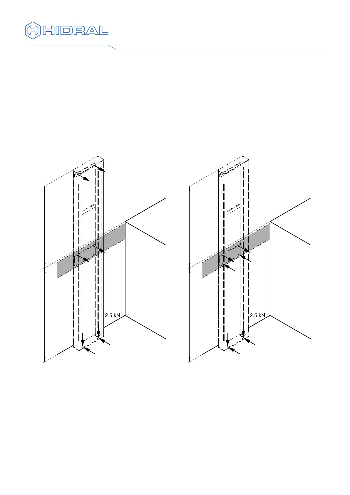
3 Verify the characteristics of the wall to which the guide shall be xed. The guide is
designed to be xed to the oor, to the slab of the upper landing level and on the
upper end of the guide. In case a resistant enough support is not available for the
xation on the upper end of the guide the two upper xations may be moved to the
central xation plate to the slab. The reaction forces of the guide assembly on the
oor and xation wall are indicated in the following drawing.
With xation on the upper
end of the guide
Only with xation to the slab
of the upper landing level
2.5 kN
2 kN
2 kN
0.6 kN
2 kN
0.6 kN
2 kN
R 1100
2.5 kN
2 kN
2 kN
20 kN
20 kN
R 1100
20 kN
20 kN
 Loading...