Design and functions | 4
Hidrostal AG 21 / 49
The following conditions must then be adhered to: When the temperature
limiter responds, the pump must switch off immediately and must NOT start
again automatically after cooling down. Before the pump is started up again,
the cause must be investigated and the fault(s) eliminated, noting that
repairs may only be performed by authorised trained personnel.
Moisture sensor (BN3, BK3
only; option):
The moisture sensor monitors the seal at the medium side for leakage. The
sensor and the electronic evaluation system measure the electrical
resistance of the sealing medium. The resistance decreases as the water
content in the sealing medium increases. The electronic evaluation system
can trigger an alarm when a value of 60kOhm is reached. These sensors
can be evaluated to provide additional pump protection, and to initiate a
precautionary shutdown.
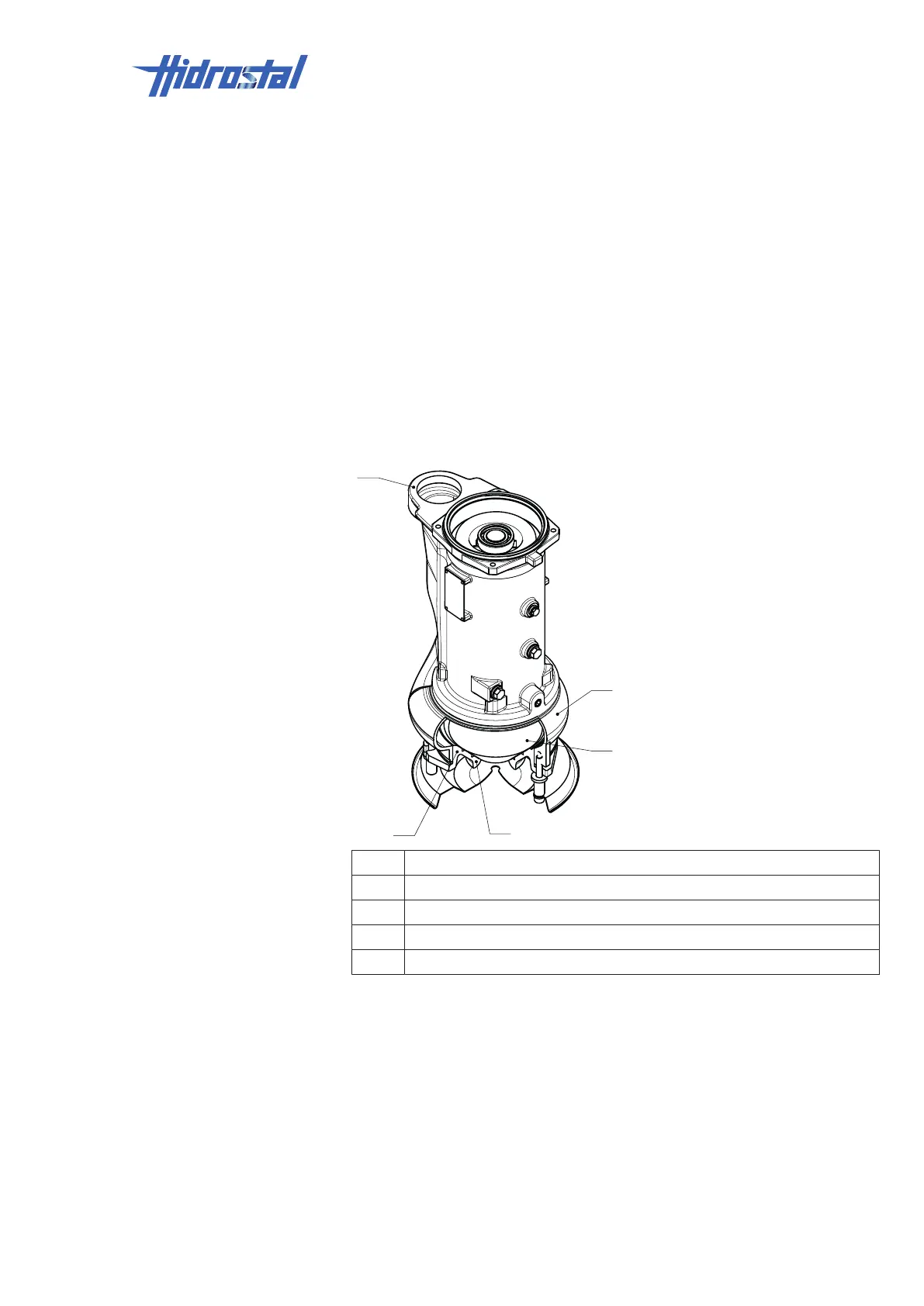
4.4 Hydraulics
1 Suction cone
2 Screw centrifugal impeller (impeller)
3 Pressure flange
4 Spiral casing
5 Suction flange
4.5 Connections
The pump is connected to the energy supply by means of one or more
electrical cables. See Appendix [▶49] for the wiring diagram.
The design and documentation of the system's internal connections are the
responsibility of the system manufacturer and are not covered in these
operating instructions.