Chapter 3. Wiring and Signals
3-19
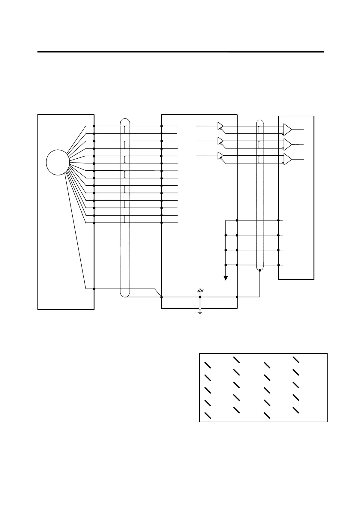
[Example of wiring between motor side (□130, 180 series) and FDA6000C CN2 when
incremental encoder is used]
2-12
EN
A
B
C
D
E
F
K
L
M
N
P
R
H
G
J
P
P
P
P
P
P
Motor side(□130,□180)
INCREMENTAL ENCODER
2-18
2-15
2-16
2-13
2-14
2-11
2-5
2-6
2-3
2-4
2-1
2-2
2-19
2-9
PA
/PA
PB
/PB
PZ
/PZ
PU
/PU
PV
/PV
PW
/PW
Vcc(5V)
GND(0V)
CN2 CN1
Controller
1-7
1-32
1-6
1-31
1-5
1-30
AC SERVO DRIVER (FDA6000C)
1-1
1-8
1-33
1-34
0V
PA0
/PA0
PB0
/PB0
PZ0
/PZ0
P
P
P
Applicable
line receiver
TI SN 75175
Output LINE DRIVER
TI SN75174
[*1]
[*1]
[*2]
1-50
[*1] P indicates twist pair wire
[*2] T.I TEXAS INSTRUMENT
[CN2 wiring diagram]
P
3.4.2 Wiring diagram of CN2 using absolute encoder
CN2 is a connecter located in the right center of the
front part of the drive system. This is used to connect
the drive system and servo motor encoder.
The right figure shows pin array viewed from the user
connector. Encoder signal varies slightly according to
the types of encoder.
Based on the soldered side of the user connector)
13:/PB
9:GND
11:/PZ
8:BT-
12:FG
10:
14:PZ
16:PB
18:PA
17:
15:/PA
19:Vcc
20:ERST
PIN array of CN2
1:RX
3:
5:
4:/
2:/RX
6:/
7:BT+