3. Parameter setting
3-4
<For digital loader >
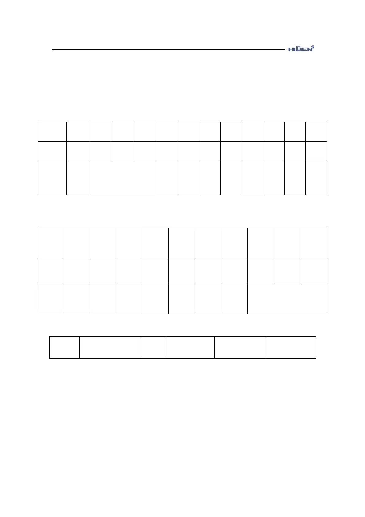
The following table shows the PIN allocation based on the manufactured default value.
CN1 PIN
No.
(Input)
18
(SVON
EN)
43
(SPD1)
17
(
SPD2)
42
(
SPD3)
16
(
DIR)
41
(
PI/P)
15
(CCW
LIM)
40
(
CWLIM)
14
(SPDLIM
/TLIM)
39
(
ESTOP)
13
(
STOP)
38
(ALM
RST)
Example
1 1 0 0 0 0 0 1 0 1 0 0
Operation
content
Motor in
operation
Internal command speed 1
selection
Command
direction
revolution
PI
control
operatio
CCW
revolution
possible
CW
revolutio
impossibl
e
Speed/
torque
limit not
used
Not
used
Not
used
Not
used
CN1 PIN
No.
(Output)
23
(
-)
48
(BRAKE)
22
(
INSPD/
INPOS/
INTRQ)
47
(
ZSPD)
21
(
RDY)
46
(SPDOUT/
TRQOUT)
20
(
ALARM)
45
A_CODE0)
19
(A_CODE1
44
(A_CODE2)
Example
- 1 1 1 1 0 1 0 0 0
Operation
content
Not used
Motor
brake
cancel
Command
speed/
position/to
rque
reached
condition
0 speed
reached
condition
Servo
ready
condition
Speed/
torque
limit not in
process
Normal
condition
Normal condition
StE-18
PROG Version
Unit
-
Setting range
0.0 ~ 99.99
Manufactured
default
Speed/Torque/
Position control
This menu displays encoder type, program version and drive capacity.
* First character : Encoder type ( I = incremental type, S = serial type )
* Second character : Drive capacity ( S = small, 8 = middle, L = large )
* Remainder character : software version
(Ex : SS 1.15 = Serial encoder, small capacity drive, S/W version 1.15)