Video Intercom Module Door Station·User Manual
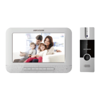
The mounting frame should be placed exactly as below for this step. The tamper plate
should be at the low right of the first grid.
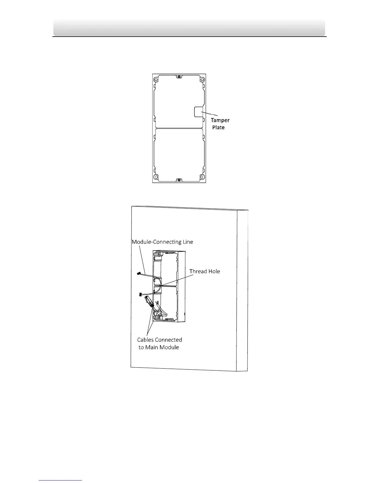
5. Thread the module-connecting line across the thread hole of the frame.
Pass the main unit connecting lines across the thread hole to the upper grid.
Figure 4-15 Placement of Lines
6. Connect the cables and module-connecting line to the corresponding interfaces of the
main unit, then place the main unit into the upper grid.
Connect the other end of the module-connecting line to the input interface of the
sub module.
Organize the line with cable tie in the package. The suggested line connection picture
as below.

 Loading...