F3 DIO 8/8 01 3 Product Description
HI 800 179 E Rev. 2.00 Page 13 of 52
3.1.2 Safety-Related Digital Outputs
The remote I/O is equipped with 8 digital outputs DO+ (ground L-) and 2 digital outputs DO-
(ground S+). The state (HIGH, LOW) of each output is signaled by an individual LED (HIGH,
LOW).
At the maximum ambient temperature, the DO+ outputs 1...3 and 5...7 can be loaded with 0.5 A
each, and DO+ outputs 4 and 8 can be loaded with 1 A or with 2 A at an ambient temperature of
up to 40 °C.
At the maximum ambient temperature, the DO- outputs 4- and 8- can be loaded with 1 A each
or with 2 A at an ambient temperature of up to 40 °C.
Within a temperature range of 60…70 °C, all outputs of the F3 DIO 8/8 014 can be loaded with
0.5 A, see Table 15.
The digital ou
tputs DO4+, DO8+, DO4- and DO8- can be connected as one-pole or 2-pole
switching connections. The remaining outputs are only set up for one-pole switching
connections.
With 1-pole switching outputs, ensure that the system's L- ground from the corresponding
channel group is used for the DO+ outputs and the system's S+ ground is used for the DO-
outputs, see Table 18. The S+ ground is limited by the system to a
maximum current of 8 A and
obtained from the 24 V voltage connection.
The external wire of an output is not monitored, however, a detected short-circuit is signaled.
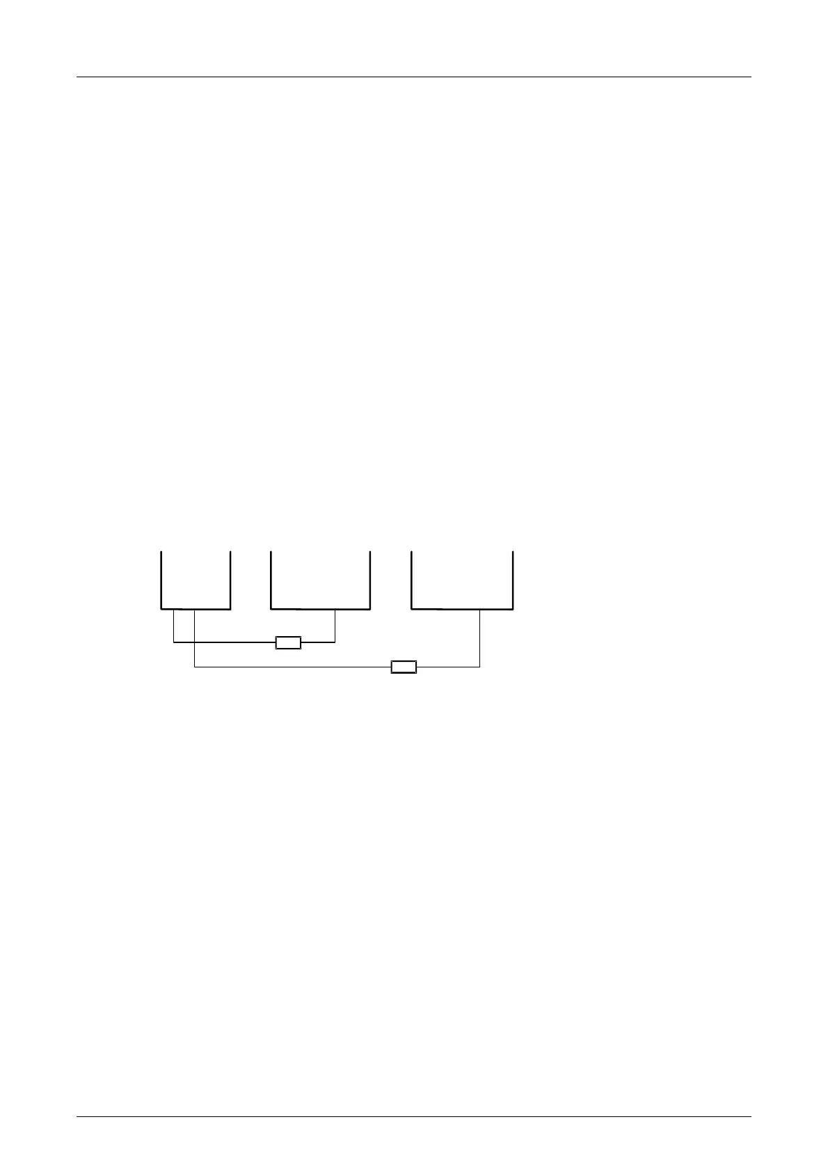
With 2-pole switching outputs, the L+ switching output DO4+ must be connected to the L-
switching output DO4- and the L+ switching output DO8+ to the L- switching output DO8-. This
type of connection must be set via the DO2[xx].2-pole system parameter.
S+
DO8-
DO4-
DO4+
L-
L-
DO8+
Figure 3: Connection to the 2-Pole Switching Outputs (DO-, DO+)

 Loading...


